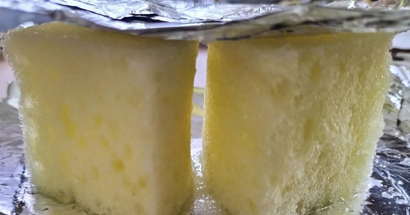
冷水を染み込ませ塩を振りかけたスポンジキャパシタ

【電解質水で作るスポンジキャパシタ型電極間の導電性】
【はじめに】
近年、電子デバイスは微細構造化の研究が進んでいる。しかし微細化の検討の前にセンチメートル級のモデルで考察実験することは基本設計をする上で重要だと考えている。
微細構造デバイスの典型例であるメモリキャパシタについての課題や可能性を議論するためセンチメートル級キャパシタをスポンジで作り、抵抗値測定や断面観察を行った。
絶縁体を上下を電極で挟み込んだキャパシタ構造は電気デバイスで多用される構造体の1つだ。半導体デバイスでは微細化したキャパシタに貯めた電荷からオン・オフを判定するメモリ部分に使われる。
この絶縁体キャパシタを多結晶体で作ると絶縁破壊するリーク電流は特徴的な弱点で技術課題だ。微細なデバイスでのリーク電流も、スポンジを使ってセンチメートル範囲に拡大してモデル化できると考えた。
ウレタン発泡スポンジを絶縁体部分に使いキャパシタを作製した。乾いたウレタンフォームはアルミホイルで挟み込んでも電気抵抗値は十分高く市販テスターでの抵抗測定では測定範囲より上だ。このスポンジキャパシタに冷水、塩水を染み込ませると絶縁性は示さなくなる。ウレタン発泡スポンジ自体は絶縁体であることに変わりはない。外側に表面張力でできる電解質液が導電性担う。絶縁体材料自体は変わらなくてもその絶縁体材料の外側の表面状態によって電気特性が劇的に変わり得る。


巨視的キャパシタを使って電解質液体が絶縁体固体表面に薄膜状にあるモデルを使い、新規デバイスの微細構造の設計アイデアを検討した。
スポンジキャパシタの抵抗測定を行い、氷キャパシタより抵抗値が低く安定して測定できたので報告する。
【方法】
塩水を染み込ませ塩を振りかけたスポンジ電極で抵抗値を測ってみた。
電極間はおよそ40ミリ。
スポンジは扇形で40ミリ径を2つ。
弧を隣り合わた並び方に配置。
食塩水を染み込ませた。
食塩をスポンジ外側に振りかけてある。
氷塩水を染み込ませたので水温はゼロ℃付近。
テスターは端子を上部アルミホイルにタップして測るタッピング法と、端子を押し付けながら時間変化を見る方法で測った。
【結果】
テスターによる抵抗値はタッピング値で8キロオーム程度。針を当て続けると時間変化で抵抗が上がる。1分当てると12キロオーム程度から15キロオーム程度まで上がる。これは当てるとアルミが変形して接触面積が小さくなるためと考えられた。当てる力を十分小さく抑えると抵抗値は14キロオーム以下に低く保てる。
この抵抗値は塩を振りかけた氷キャパシタの抵抗値(タッピング法)22キロから50キロオームとおおよそのオーダーは一致している。スポンジタイプのほうが3割から7割程度小さい。
氷キャパシタにテスターを長く当てると抵抗値は上がり続ける。タップで20キロΩを示しても数秒後には10倍以上に上がり、1分以内には2000キロΩを超えて測定できなくなった。氷と上部アルミホイルとの界面は不安定で接触面積が小さくなるように見られた。
スポンジキャパシタとの比較すると以下のような推測ができる。
スポンジ上部が平坦でアルミホイルとの接触面積が確保できる。
低温の塩水電解質が十分な導電性を確保している。
その低温電解質液はスポンジの上下間を表面張力で液で濡らして結んでいる。
ウレタンフォーム自体の抵抗値に変化はなく、ウレタンフォーム表面や内部の泡部分の表面を覆う液体薄膜電解質が導電性を担っている。
ウレタンフォームキャパシタの観察写真を示した。キャパシタ下部に食塩が観察され電解質が十分にあることがわかる。スポンジ内は電解質水で満たされておらず液滴も観察されない。
【考察】
絶縁体キャパシタの電極間の電流は電解質液体があるか、ないか、で100倍以上に上がる。抵抗値が14キロオームの電解質スポンジと2000キロオーム以上の乾燥スポンジの抵抗が異なるキャパシタに対応する。
電解質液体は発泡ウレタンの内部と表面の泡の表面部に存在して、上下電極の導通を担っている。電解質液は液滴状には観察されない。ウレタンスポンジの表面に吸着する形で薄膜状に液が存在している。
スポンジ内の表面の液体膜は粘性を調整可能である。ゼリー状にすれば機能性の微粉末を固定できる。コンデンサの絶縁体に加えて別の物理特性のある粉末を使った新しいデバイス設計ができる。薄膜絶縁体のサイズに比べて微細粉末のサイズは小さくしやすい。また、機能性と絶縁性を分けて設計できれば自由に設計しやすくなる。
【まとめ】
巨視的キャパシタを使って電解質液体が固体表面に薄膜状に配置されたデバイスをモデル化した。
絶縁体材料と電極との界面を平滑に設計すると電極間の抵抗値が測定中に上がらずに安定した。
絶縁体材料の表面の低温電解質液体が電極間の導電性を担い抵抗値は14キロオーム程度だった。
塩を振りかけた氷キャパシタの抵抗値と同じオーダーで、3割から7割低い抵抗値だった。
絶縁体の表面にある液体電解質液の粘性や機能性を設計して新規デバイスを作る指針を提示できた。
Measuring the resistance of a capacitor made with salt water and a sponge
Introduction
In recent years, research on microstructuring of electronic devices has been progressing. However, I believe that it is important for basic design to consider and experiment with a familiar centimeter-scale model before examining miniaturized devices.
The capacitor structure, in which an insulator is sandwiched between electrodes on the top and bottom, is a structure often used in electrical devices. In semiconductor devices, it is used in the memory part that determines on/off from the electric charge stored in the miniaturized capacitor.
For memory capacitors, which are a typical example of microstructured devices, it is possible to discuss issues and possibilities in capacitor structures from a centimeter-scale model.
In this study, we fabricated a capacitor using centimeter-sized urethane foam sponge for the insulator part, measured the resistance, and observed the cross section. The electrical resistance of the dry urethane foam was sufficiently high even when sandwiched between aluminum foil, and was above the range of resistance measured with a commercial tester.
Urethane foam sponge is an insulator, and even when sandwiched between aluminum foil, its electrical resistance is high enough to be above the range of resistance measured by commercial testers. When this sponge capacitor is soaked in cold water or salt water, it no longer exhibits insulating properties. The urethane foam sponge itself is still an insulator. The electrolyte solution that forms on the outside due to surface tension is the conductive carrier. Even if the insulator material itself does not change, the surface condition of the outer surface of the insulator material can dramatically change its electrical properties.
Such insulator leakage current is a characteristic of polycrystalline insulator capacitor devices. We believe that leakage currents in nanometer-range microscopic devices can also be modeled in the centimeter range using sponges.
Using macroscopic capacitors to model devices in which the electrolyte liquid is arranged as a thin film on a solid surface will be useful in examining microstructures and novel devices.
We report on the resistance measurements of a sponge capacitor to investigate an enlarged model of a thin liquid electrolyte that can be used for microstructures and novel devices.
Methods
Resistance was measured using sponge electrodes soaked in salt water and sprinkled with salt.
The distance between the electrodes was about 40 mm.
Two 40 mm diameter sponges were placed in a fan shape.
The arcs are arranged in an adjacent sequence.
The sponges were soaked in salt water.
Salt was sprinkled on the outside of the sponges.
The water temperature is around zero degrees Celsius because the sponge is soaked in ice brine.
Result.
The tester resistance is about 8 kilo-ohms at the tapping value. If the needle is applied for one minute, the resistance increases from about 12 kilo-ohms to about 15 kilo-ohms. This is thought to be due to the deformation of the aluminum when the needle is applied, resulting in a smaller contact area. If the force of application is kept sufficiently small, the resistance value can be kept below 14 kilo-ohms.
This resistance is roughly on the same order of magnitude as the resistance of an ice capacitor sprinkled with salt, which is 22 to 50 kilo-ohms. The sponge type is about 30% to 70% smaller.
The reasons for this are as follows.
The top of the sponge is flat, allowing for a larger contact area with the aluminum foil.
The low-temperature brine electrolyte has sufficient conductivity.
Because the low-temperature electrolyte liquid is wetted by the liquid and connected between the top and bottom of the sponge by surface tension.
There is no change in the resistance of the urethane foam itself, and the liquid thin-film electrolyte covering the surface of the urethane foam and the foam part inside is thought to have been responsible for conductivity.
The following is a photograph of a urethane foam capacitor. The salt is observed at the bottom of the capacitor, indicating that there is sufficient electrolyte.
Discussion
The current between the electrodes of an insulator capacitor increases more than 100 times depending on whether there is electrolyte liquid or not. The electrolyte sponge with a resistance of 14 kilo-ohms and the dry sponge with a resistance of over 2000 kilo-ohms correspond to capacitors with different resistances.
The electrolyte liquid is present inside the urethane foam and on the surface of the foam and is responsible for the conduction between the top and bottom electrodes. The electrolyte liquid is not observed in droplet form. The liquid exists in the form of a thin film adsorbed on the surface of the urethane sponge.
The insulator material on the surface of the sponge capacitor, where the electrolyte liquid exists in thin film form, has the potential to support other functional powder materials. If magnetic iron particles, among others, can also be loaded, the magnetic particles placed in the surface liquid of the insulator material of such a capacitor can be expected to exhibit unique electromagnetic properties. The magnetic powder arranged in a semi-fixed and semi-fluid form so that its electromagnetic properties can be detected by upper and lower electrodes is expected to be applied to new magnetic devices and antennas.
The state of fixation of the fine particles differs from that of conventional devices of iron fine particles fixed in a solid thin film. The iron particles suspended in liquid thin films and semi-fixed iron particles in gelatinized thin film electrolytes can be designed, which will behave differently from conventional electromagnetic wave properties.
Summary.
A device in which the electrolyte liquid is placed in a thin film on a solid surface was modeled using a macroscopic capacitor.
When the interface between the insulator material and the electrode was designed to be smooth, the resistance between the electrodes did not increase during the measurement and stabilized.
The low-temperature electrolyte liquid on the surface of the insulating material provided conductivity between the electrodes, and the resistance was about 14 kilo-ohms.
The resistance was on the same order of magnitude as that of an ice capacitor sprinkled with salt, and 30 to 70 percent lower.
The viscosity and functionality of the liquid electrolyte solution on the surface of the insulator could be designed to provide a guideline for creating novel electromagnetic wave devices.
この記事が気に入ったらサポートをしてみませんか?