Interference Pattern Formed in a Finger Gap is NOT Single Slit Diffraction

Simple way of making an interference pattern with fingers
The phenomenon of forming an interference pattern by using light that passed through a double slit is a basic item learnt in a high school physics course. It is a good example that light possesses a property of waves. The double slit experiment can be easily conducted by using coherent light such as lasers. But, if you are to use a readily available light source such as sunlight and room illumination, you need to be a little bit creative (discussed below).
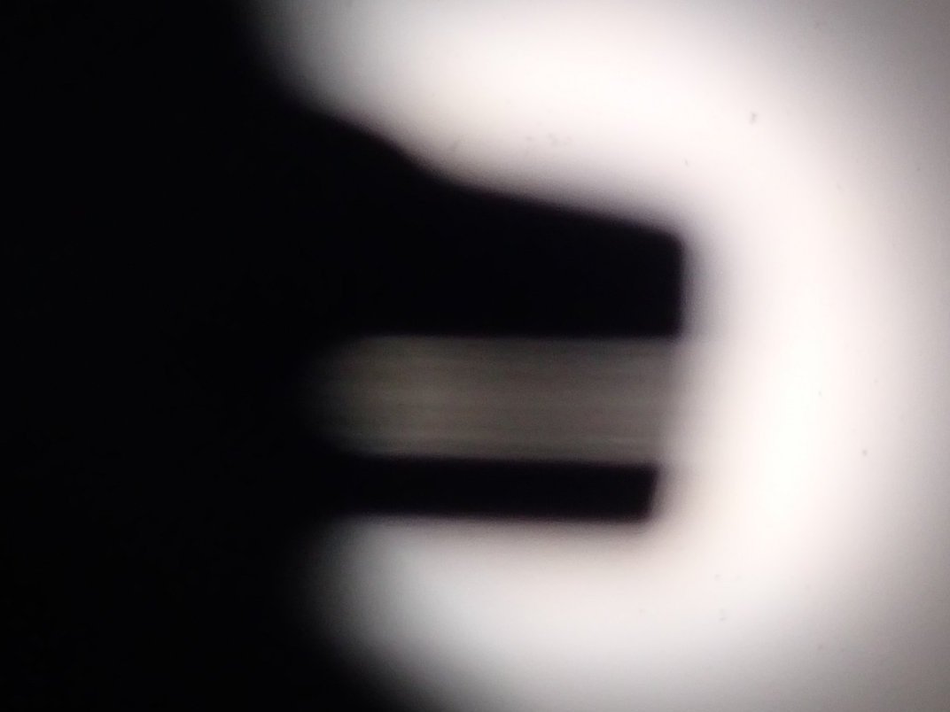
However, there is a simple way to create an interference pattern by using such easily available light sources. Make a very narrow gap between two fingers, and peep the room illumination or sunlight through the gap. Put the finger gap about 10 cm ahead of your eye, and keep focusing your eye at the illumination. If you narrow the gap to superimpose the blurred edges of the fingers, you will find a very fine interference pattern within the superimposed shadow area. I managed to take a photo of the pattern with a compact digital camera (below).
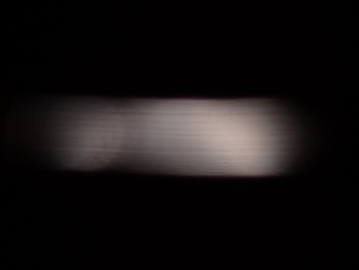
I put the camera behind the finger gap, and took the photo with a digital camera (Olympus TG-5). The pattern can be seen more clearly by visual observation. I wonder if anyone else has tried to do the same.
Now, the problem is the physical principle of the formation of the interference pattern. If you do a search on the Net, you'll find some articles that explain it by single slit diffraction. I've also thought so until recently. On reconsidering the matter, however, it is not that simple. As far as my reconsideration and what I've understood, this phenomenon is not single slit diffraction but "diffraction by a semi-infinite screen." Although both are phenomena of optical interference, they differ in basic properties such as the relation between the gap width and the period of the stripe pattern. I try to explain the principle below with little use of math expressions.
Basics of diffraction
What's diffraction?
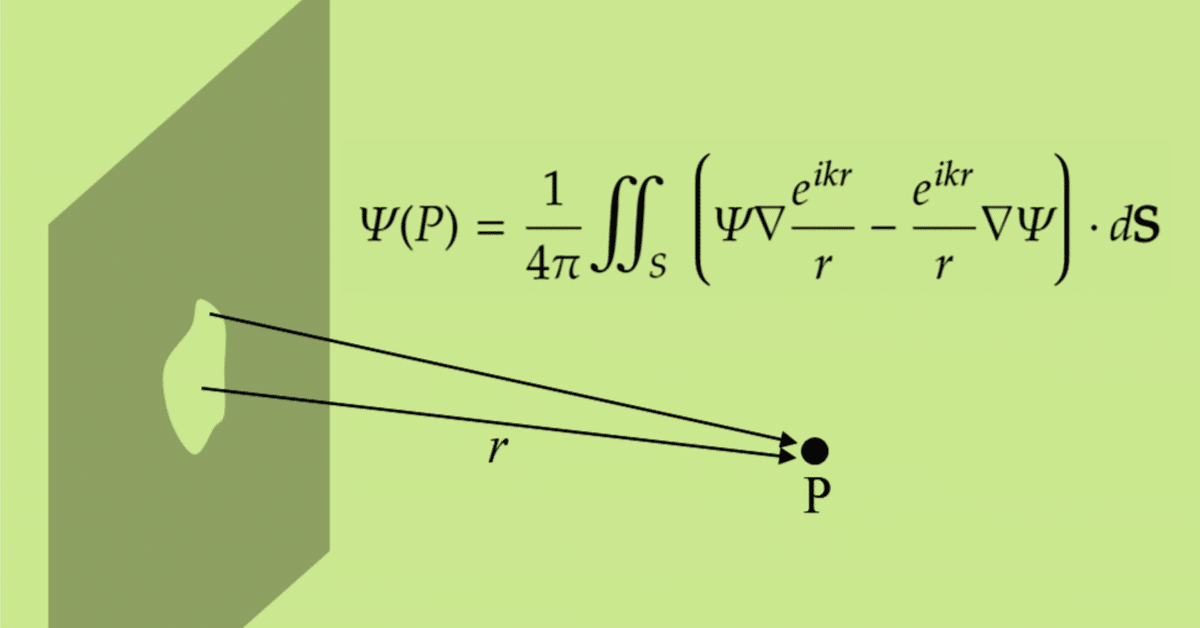
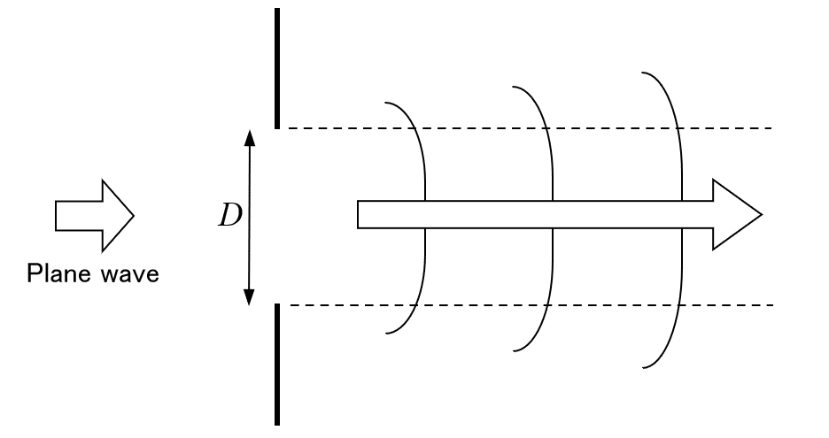
Diffraction is a phenomenon that the a propagating wave bends at the corner of a barrier and goes around behind it. In the case of an electromagnetic wave, the phenomenon is formulated by a theory of diffraction by Fresnel and Kichhoff. Its formula can be derived from the Helmholtz equation by imposing a boundary condition of the barrier, but the way to the formula from the introductory electromagnetism is long. (When I entered the department of physics in the second year of the university, I learnt the derivation of the formula. I was shocked at the sudden surge of the difficulty level.) But the meaning of the consequence is intuitively easy to understand. As shown in the figure below, when a plane wave comes behind the aperture of a screen, the aperture, when seen from the downstream, looks like a set of many point light sources, and a coherent spherical wave comes from the each point source. It is expressed by the Kirchhoff's integral theorem.
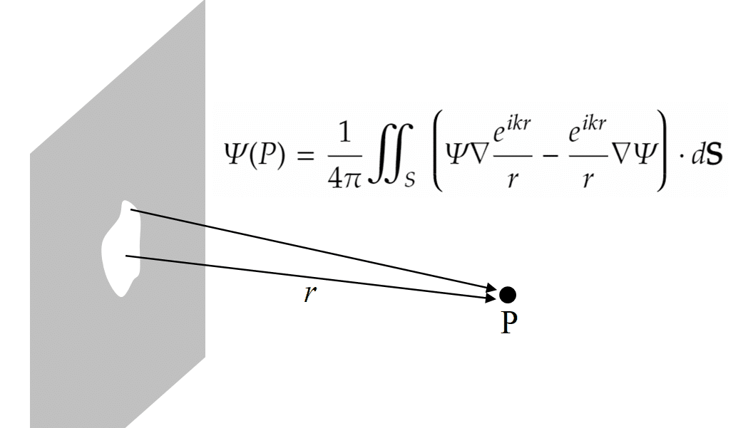
Its meaning is that the electromagnetic wave at the point P is expressed by a sum of spherical waves that come from all the points on a closed surface that surrounds the point P. It corresponds to a mathematical formulation of the Huygens principle. When the light source is behind the screen, the points that contribute to the integral are actually only within the aperture.
The light intensity distribution depending on the output direction from the aperture can be obtained by solving the integral equation in principle. When we want to know only the position of the bright and dark lines of the interference pattern on the screen at the downstream, however, we do not have to go to all that trouble. We can obtain it by a simple way that we learned in the high school physics course.
In the case of a double slit
This is a well-known problem learnt in the high school physics. When coherent light is injected into a pair of parallel slits, it projects a interference pattern on a screen at the downstream of the slits. In this case, since the width of each slit is sufficiently smaller than the distance between the slits,
the double slit can be considered as a pair of point sources (or "line" sources).
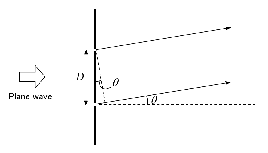
Let $${\lambda}$$ be the wavelength of light, and $${D}$$ the distance between the slits. The optical path difference from the two slits at the output angle $${\theta}$$ is $${D\sin\theta\simeq D\theta}$$ (Fig. 3). If this is equal to the integral multiple of the wavelength $${\lambda,}$$ the two light waves are in the in the same phase and reinforce each other. If it is equal to the (integer + 1/2) multiple of $${\lambda,}$$ the two light waves are superposed in the opposite phase and cancel out each other. Therefore, the positions of bright and dark lines are
bright line at $${\theta_n = n\lambda/D,}$$
dark line at $${\theta_n = (n+1/2)\lambda/D,}$$
where $${n = 0, 1, 2, \cdots.}$$ The period of the stripe pattern is given by $${\lambda/D}.$$ Note that the period of stripe becomes larger as the slit gap $${D}$$ becomes narrower. They are inversely proportional to each other.
In the case of a single slit
Next, we consider the case of a single slit. In this case, since there is only one slit, what matters is not the gap between two slits but the width of the single slit. Unlike the case of the double slit, the single slit can be considered as a set of parallel "line" light sources that are densely collected within the slit aperture. Then, we have to consider the superposition of light waves coming from all the line sources. It may seem complicated, however, on careful reflection, we can use the same the same solving method as that for the double slit case.
This problem may be easily understood if we consider the condition of forming dark lines. Let $${D}$$ be the slit width. There is obviously a bright line at $${\theta=0.}$$ Now, increase the output angle $${\theta}$$ gradually from $${\theta = 0.}$$ As $${\theta}$$ becomes larger, the intensity of the light wave becomes smaller due to the increasing contribution of waves with different phases. Then, at what angle $${\theta}$$ does the first dark line appear? The answer is when $${(D/2)\theta=(1/2)\lambda}$$ holds as shown below.
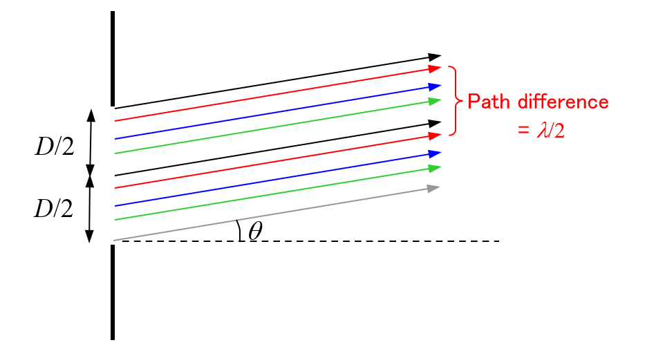
Since the path difference of each pair of waves of the same color is half wavelength, all the waves cancel out.
Because, on this condition, the following properties hold:
Since any pairs of light waves whose distance between them at the aperture was $${D/2}$$ are in the inverse phase, they cancel out each other;
For any incident waves at arbitrary positions at the aperture, there necessarily exist incident waves which are incident at a distance of $${D/2}$$ away from the former.
Therefore, it results in canceling out of all the light waves. Similarly, if we increase the output angle $${\theta}$$ even more, dark lines appear when the following condition holds:
$${(D/2)\theta=(n+1/2)\lambda,}$$ $${n = 0, 1, 2,\cdots.}$$
Moreover, in Fig. 5, even if we divide the aperture into not two but four parts, the output waves cancel out. Therefore, dark lines also appear on the following condition:
$${(D/4)\theta=(n+1/2)\lambda,}$$ $${n = 0, 1, 2,\cdots.}$$
Similarly, it is also the case for dividing into 8, 16, $${\cdots}$$. As a result, the positions of dark and bright lines are summarized as follows:
dark line at $${\theta_n = n\lambda/D}$$ (the conditions mentioned above are summarized as this formula);
bright line at $${\theta_0=0}$$ and $${\theta_n = (n+1/2)\lambda/D}$$ (bright lines comes between the dark lines).
where $${n = 0, 1, 2,\cdots}$$. Although the period of the stripe is $${\lambda/D}$$ as in the case of the double slit, the width of the bright line at $${\theta_0=0}$$ is specially twofold. The period of stripe becomes larger as the slit gap $${D}$$ becomes narrower, inverse-proportionally. This is same as the case of the double slit.
Intense distribution of interference pattern
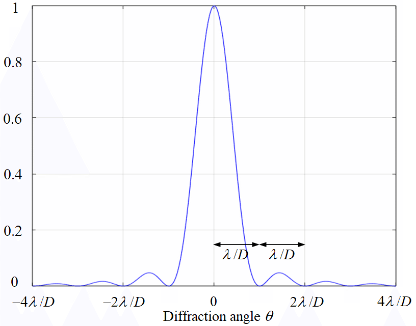
By using the simple method mentioned above, what we can argue is only the location of bright and dark lines. To obtain the intensity distribution of an interference pattern, we have to return to the Kirchhoff's integral theorem. If we suppose some realistic conditions, we can obtain a good approximate solution from the theorem. The result is shown below. In the case of single slit diffraction, since the 0th bright line is extremely intense, it is actually difficult to observe the stripe pattern.
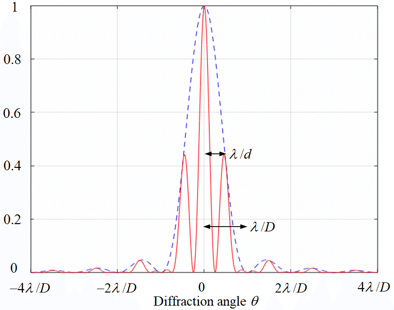
In the case of double slit diffraction, since the double slit is a combination of a pair of single slits, its intensity distribution appears as a multiple of a large stripe (formed by the single slit) and a fine stripe (by the double slit). Since the slit width is smaller than the gap between the two slits, the period of stripe formed by the single slit is larger than that by the double slit. The obtained result in the case of the slit width $${D}$$ and the slit gap $${d=2D}$$ is shown below. The stripe can be observed more easily than that of the single slit.
What is the interference pattern formed in a finger gap?
Explainable by single slit diffraction?
Now, get back to the original problem. What physics causes the interference pattern in a finger gap? Since there is only one gap in this case, is it single slit diffraction? Actually, it is not that simple. In the case of single slit diffraction, an extremely bright line should emerge at the center. However, there is no such line in the real pattern as shown in Fig. 1. The stripe pattern is roughly uniform within the gap.
Moreover, in the case of single slit diffraction, the period of stripe is inversely proportional to the slit width. In other words, as the slit width become narrower, the period of stripe must become larger. However, it is not actually the case. Even if the finger gap is narrowed while peeping the illumination through it, the period of stripe does not seem to change at all.
Using fingers may not show it clearly. So I used a nail clipper in place of fingers to make the gap. Photos of the stripe pattern appeared when peeping a fluorescent light through the gap between the edges of a nail clipper are shown below.
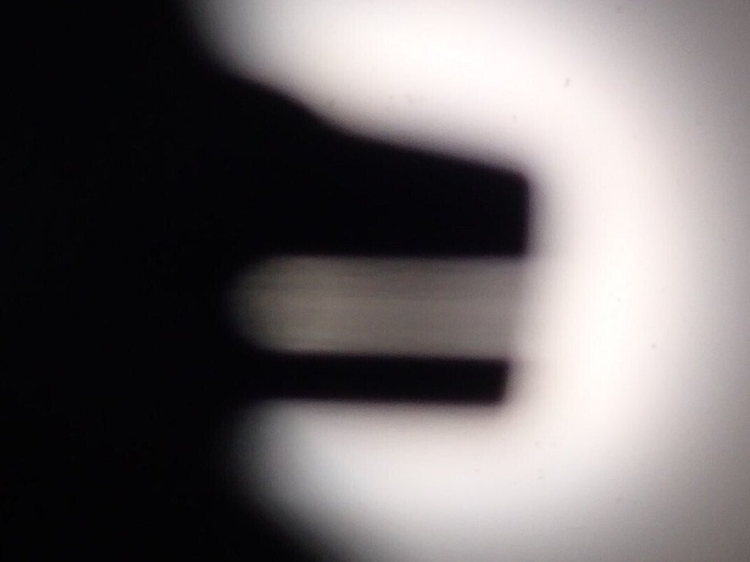
Although the gap width in Fig. 9 was at least 1.5 times larger than that in Fig. 8, the stripe patterns are almost the same. The period of stripe did not change. As the gap was widened, only the brightness of the pattern slightly increased, and the contrast of the stripe slightly decreased.
Besides, even if we put a realistic value into the period of stripe $${\Delta\theta=\lambda/D,}$$ it does not match the reality. Let the wavelength of light be $${\lambda=500\,\text{nm},}$$ and the slit width $${D=0.1\,\text{mm},}$$ and suppose that we observe the interference pattern which was projected at $${L=10\,\text{cm}}$$ ahead of the slit. The period of stripe is calculated as
$${\Delta x=L\Delta\theta=L\lambda/D\\\quad\ \ \,=10\,\text{cm}\times500\,\text{nm}\,/\,0.1\,\text{mm}\\\quad\ \ \,=5\,\text{mm}.}$$
Considering that the pupil diameter is about 3 mm, this is obviously too large.
Diffraction by a semi-infinite screen
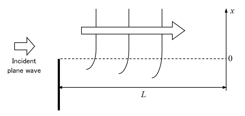
According to these observations, it seems that the period of the stripe pattern does not depend on the slit width, and is determined by other factors. Is there any phenomena of diffraction that behave like that? Then, I pulled out the book "Principle of Optics" by Born and Wolf at the library of my office, and found a description about diffraction by a semi-infinite screen. As shown in the figure below, it is the diffraction that occurs when an incident plane wave is intercepted by a semi-infinite long screen.
The diffracted wave not only goes around behind the screen, but forms a interference pattern. (Though I hold a PhD in physics, I didn't know it.)
As shown in the figure above, Let us consider the intensity distribution of light projected on the wall which is at a distance of $${L}$$ from the interception screen. Let $${\lambda}$$ be the wavelength of light, and $${x}$$ the coordinate on the wall. ($${x = 0}$$ is located at the right in front of the edge of the semi-infinite screen.) Then, according to the book, the intensity distribution becomes like the figure below.
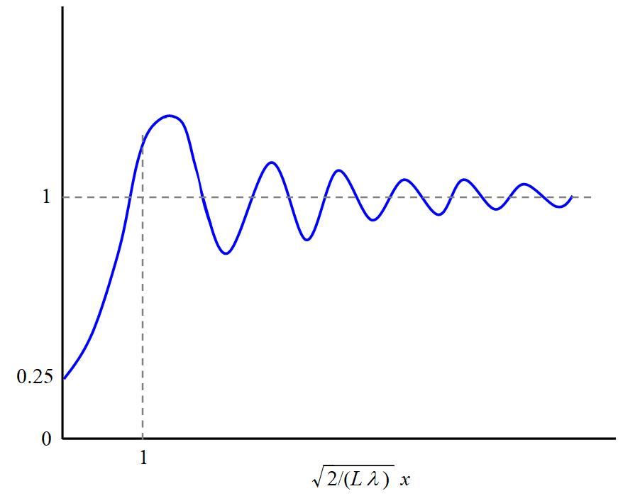
In the case of the diffraction by a semi-infinite screen, the diffracting agent has no feature values with a dimension of length, such as a slit width. Other feature values with a dimension of length are only the wavelength and the distance between the screen and wall. Therefore, the period of the interference pattern (not perfectly periodic, in this case) is necessarily determined by the ratio of $${\lambda}$$ and $${L}$$. This is a distinctive feature of this diffraction.
Derivation of the pattern of Fig. 11 is rather complicated. Fresnel integrals and the Cornu spiral are coming out on the book. (Surprisingly there exists the exact solution!) However, the reason why the first peak of the stripe roughly comes at $${x \simeq \sqrt{(L\lambda)/2}}$$ can be intuitively understood as follows (my original method).
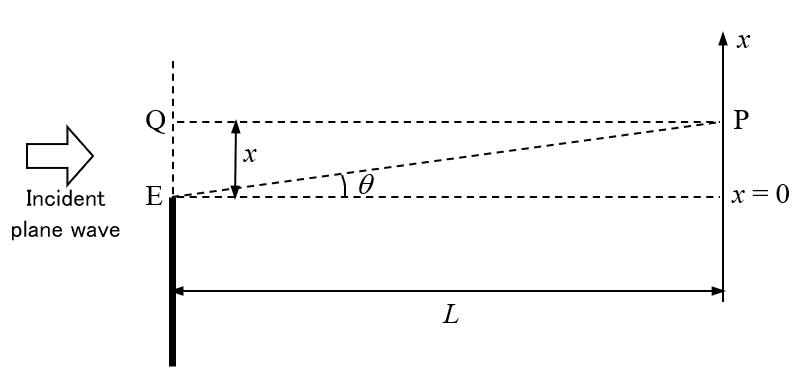
As shown in the figure above, let us consider the intensity of light at the point P which is near $${x=0.}$$ If there is not the semi-infinite screen, the light at P is a sum of all the spherical waves that come from infinite number of point sources on a infinite long line through the points Q and E. Here, since their intensity attenuates by distance, contribution from the point Q, which is right in front of P, is obviously the largest. Now, if we put the semi-infinite screen, it removes half of the spherical waves which were to reach the point P. Here, if the screen removes a wave from a point on the line segment QE, from which the optical path length to the point P is exactly larger than the distance QP by half the wavelength, the light intensity at the point P becomes higher than that before the screen was placed. Then, what is the minimum value of $${x}$$ at which this phenomenon just occurs? It is in the case that the path difference between EP and QP is exactly half the wavelength. Therefore, it is in the case that
$${x\theta\simeq\lambda/2}$$
holds. Since $${\theta\simeq x/L,}$$
$${x^2/L=\lambda/2.}$$
Therefore, we obtain $${x\simeq\sqrt{(L\lambda)/2}.}$$
By the way, the intensity distribution of Fig. 11, isn't it similar to the interference pattern formed in the finger gap?
In my opinion, this diffraction by a semi-infinite screen is exactly the physical principle of the interference pattern that appears within the finger gap. Its grounds are listed below.
Ground 1:
If you closely observe the interference pattern in the finger gap, you will find a very faint stripe pattern on the blurred edge of the finger even before you narrow the gap. As the gap is narrowed, the two blurred edges are superimposed, and there appears the fine stripe pattern. This pattern looks like the original pattern which has appeared before the gap was narrowed, but its contrast just increased. This phenomenon can be interpreted as follows. The diffraction by a semi-infinite screen has already occurred at the each edge of the fingers. When the gap was narrowed, the direction of the incident light was confined to make an effect as if the light source was minimized, which resulted in the increase of the coherence.
Ground 2:
Actually the observed stripe pattern looks very similar to the intensity distribution of Fig. 11. (The fine stripe of Fig.11 continues long to a range of larger $${x}$$ than that shown in the figure.)
Ground 3:
If you calculate the period of the stripe pattern, you can obtain a realistic value. According to Fig. 11, the period is about $${\Delta x\simeq\sqrt{L\lambda/2}.}$$ As with the case of a single slit described above, let the light wavelength be $${\lambda=500\,\text{nm},}$$ and the distance between the half screen and the observing point $${L=10\,\text{cm}.}$$ Then the period is calculated as
$${\Delta x\simeq \sqrt{L\lambda/2}\\\quad\ \ \,=\sqrt{10\,\text{cm}\times500\,\text{nm}\,/\,2}\\\quad\ \ \,=0.15\,\text{mm}.}$$
It is a realistic value considering the pupil diameter as 3 mm.
Coherent light source is not necessarily required for interference
Now, we have concluded that the interference pattern formed in the finger gap is a phenomenon of diffraction by a semi-infinite screen. I feel insecure a bit since I cannot find similar arguments on the Net. But I guess at least the outline is correct.
By the way, this interference pattern appeared in the finger gap has a distinctive feature that it can be easily seen by using readily available incoherent light sources. It is often misunderstood that coherent light is required to make an interference. (I've also misunderstood so.) However, it is not the case. Even if using a incoherent light source, interference can be made as long as the size of the light source is sufficiently small. If the size of the source is too large, the optical path length from a point on the source varies depending on its position on the source. Consequently the waves with different phases are superposed incoherently, and the interference disappears. This is avoided by just passing the incident light through a small aperture. Actually, in the famous double slit experiment by T. Young, plural single slits were installed before the double slit to obtain the same effect. In the case of making a gap with fingers or edges of a nail clipper, minimizing the size of the light source is also attained by narrowing the gap.
For the original Japanese version, refer to the following.
この記事が参加している募集
この記事が気に入ったらサポートをしてみませんか?