2step anchor

There is an update article.
Please see “15.update1” and “16.update2”.
当記事最下部に「アップデート2」があるので追加工してください。
0. preface
Hi🙋♂️everyone! How are you?
I started Mini 4wd about 4 years. I'm playing in 3lanes in Kansai region of Japan.
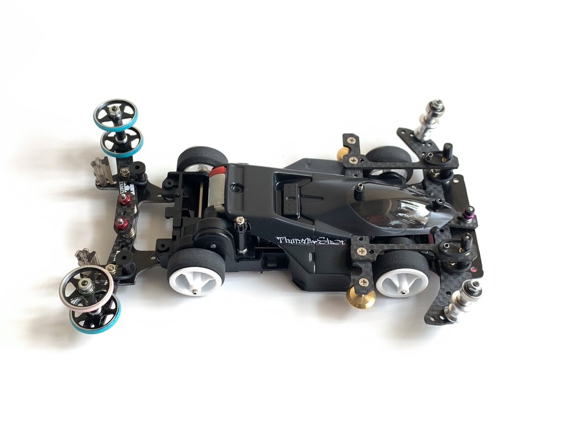
How to make a 2step anchor system.
We prioritized the completion rate and ease of making. It features a gentle landing. It is good at landing on the wave section. Since the roller angle does not change when the roller lifts up, I am also good at change lanes. And it's lightweight.
The compatibility with the rigid chassis is also quite good. The target chassis can be used for all MS suspensions, rigid chassis, single shafts, and double shafts.
Dear tester showed me a running video of 5 lanes, but the landing was soft but the cornering was sharp. It was very beautiful. MA Chassis / Fr Backslide Anchor / Rr 2step anchor
Related article💁♂️
How to make a Backslide anchor system
When installing the 2step anchor, it will be a little difficult to junp slope right after the corner, so you will need to make some simple adjustments. (For example, it is a slight change like when a slide damper is attached to the rear)
There are many techniques for making a straight jump like this. The active racers's the common sense, but those who do not know also is useful I'm sure to remember. Please see the setup method later. Let's get started🪛
こんにちはBECKです。ミニ四駆歴3〜4年。関西の3レーンで遊んでます。
お待たせしました2ステップアンカー作成編。
完走率と作り易さを優先しました。優しい着地が特徴です。ウェーブ着地にも強いです。空気ですよ。
ローラーがリフトアップする際にスラスト変化が少ないのでレーンチェンジが得意です。上側ローラーに衝撃が加わった場合は、一定入力まではバックスライドしますが、過入力の時はちゃんとアッパー方向にも捻れるようになっています。
あと軽量です。重量感あるメカメカしたギミックもワクワクするし素敵なのですが、ウチのはドシンプルが売りですね〜
壊れるか壊れないかの引き算の上に成り立つシンプル故に壊れにくいギミックは必要最小限の部品構成にしました。リジッドシャーシとの相性も最高で、対象シャーシはMSフレキ、リジッド、片軸両軸たぶん何でもOKです。
親愛なるテスターさんの5レーンでの走行動画を見せてもらいましたが、着地が柔らかくてコーナリングがシャープ。エアターンも美しかったです。(MAシャーシ / 前バックスライドアンカー / 後 2ステップアンカー)
関連記事💁♂️
バックスライドアンカーの作り方
2ステップアンカーをご装着の際、コーナー直後のスロープを真っ直ぐ飛ばすのが少し難しくなるので、簡単なリセッティングが必要になるかも知れません。(例えばリアに可動域の狭いスラダンを装置した時のような軽い変化です)
このようにまっすぐ飛ばす匠の技は色々ありまして、ベテランレーサーさんの間ではごく当たり前に共有されているような㊙︎テクニックなのですが、もし初耳の方はお役に立つので覚えておいて損はありません。後述のセッティング項でご説明いたしますね。それではどうぞ!
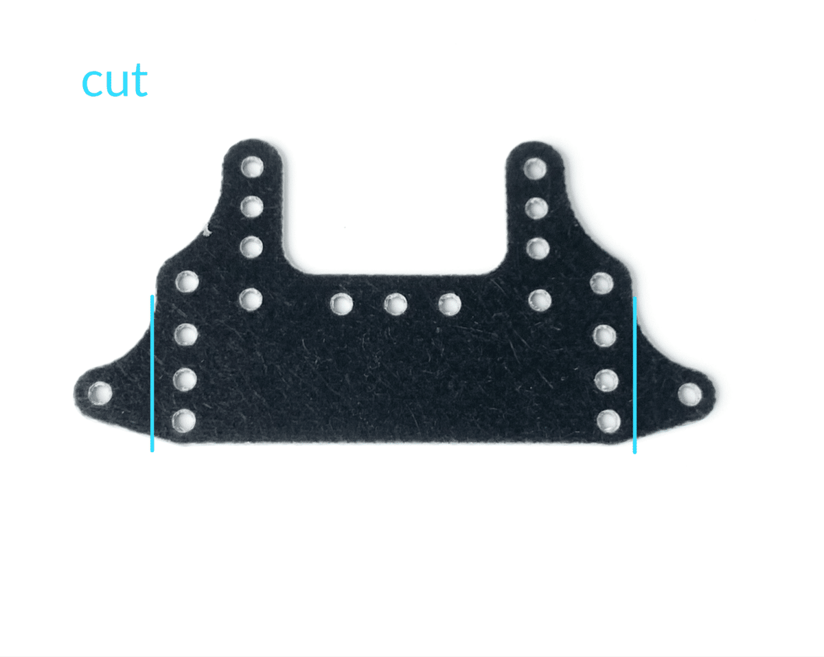
1.main plate / メインプレート

Either is OK. In the case of the left, you can attach a lot of brake sponge. The right is light weight.
どちらでもOK。左の場合はブレーキスポンジを沢山貼れるし、右は軽いですね。

If it is FRP, it will break immediately. Carbon is recommended.
FRPは壊れやすい🥲 カーボンをおすすめします。


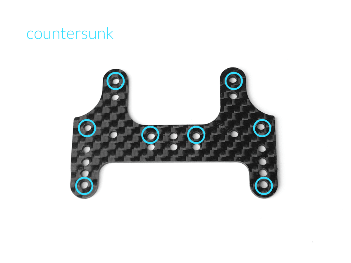
皿ビス加工

Finished ✅

👆The size and hole position are the same.
This time, I will explain on the left side.
↑サイズや穴位置はどちらも同じ。
今回は左側でご説明しますね。
2.wheel bush temporary assy / ホイールブッシュ仮組み

Enlarge to 1.8 mm after making a hole with a pin📌
ピンを挿してから1.8mmに拡大します。

2x8mm screws


Finished ✅
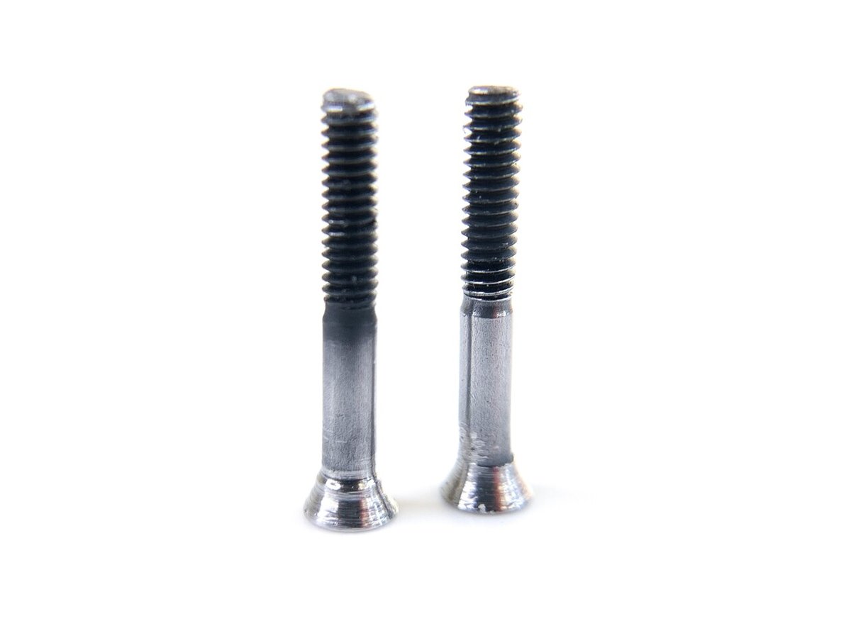
3.main shaft / メインシャフト
Please
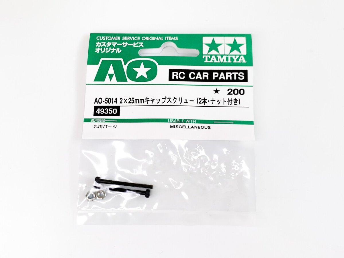
Using ordinary countersunk screws will cause malfunction. Please use by processing the 25mm cap screw.
お願い
普通の皿ビスを使うと誤作動を起こします。25mmキャップスクリューを加工してご使用ください。

2x25mm cap screws

RYOBI HR-100
毎度お馴染み神リューター!
パワー、耐久性、性能、使い易さ、コスパ最強!
もうね、全然壊れないの。
金属加工や内燃機のポート加工にも使えます。
超精密加工は… 正直微妙かも知れません笑
速度無段階調整式。
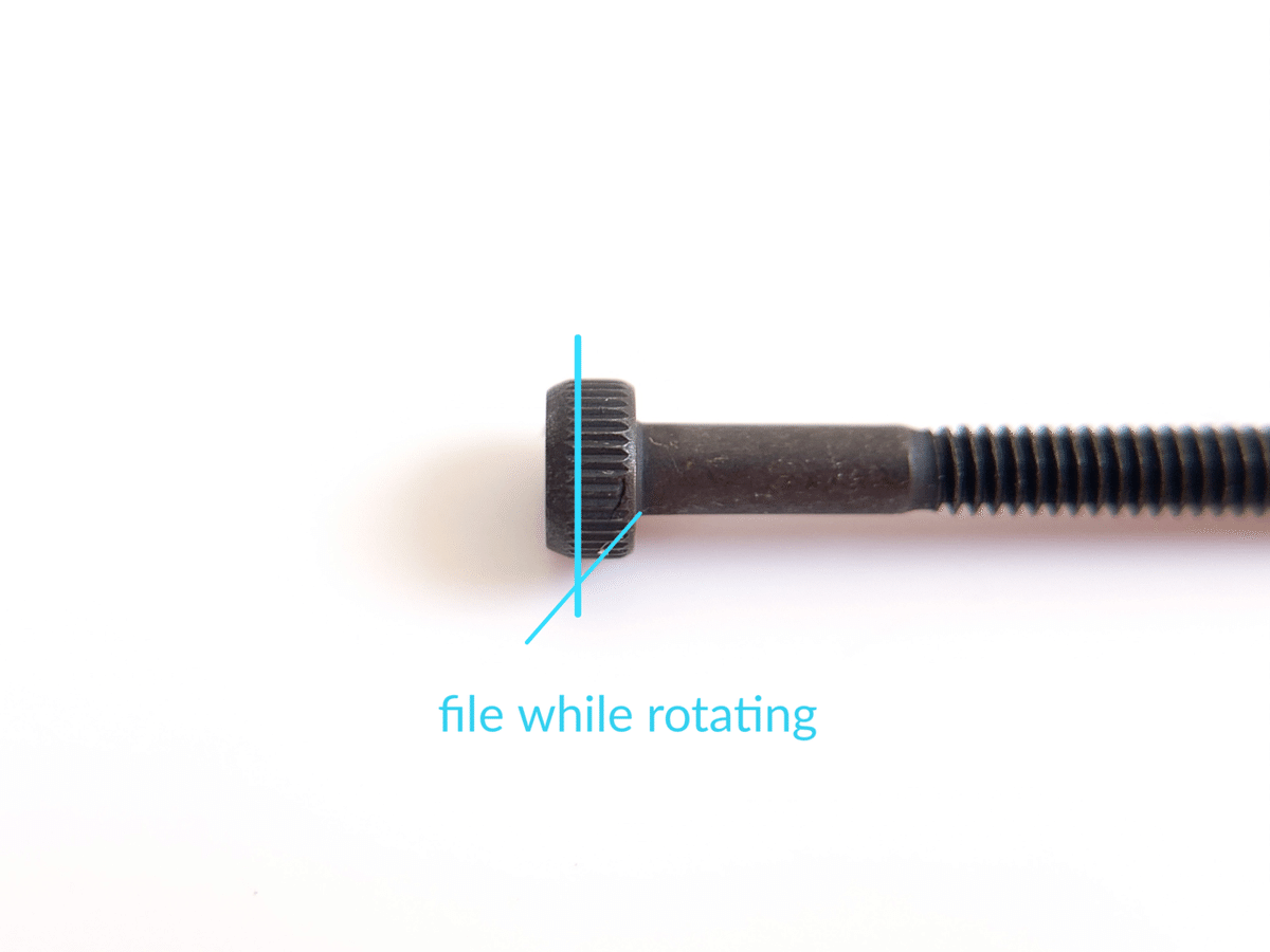
回しながら削ります

cut n polish
回しながらピカールで磨きましょう。
Finished ✅
4.connecting plate / コネクトプレート


Finished ✅
5.make a main bumper / メインバンパー作成


皿ビス加工


For 13mm rollers👆
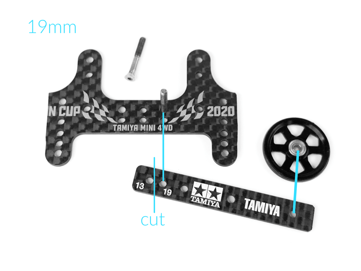
For 19mm rollers👆
I will explain with 19mm rollers.
今回は19mmローラーでご説明しますね。

2x6mm, eyelet, nut
6mmサラ、ハトメ、ナット


temporary assy
仮組み。(後で再度分解します)
Postscript
You can change the tension of the O-ring by offsetting the eyelet screw position slightly outward.
追記
ハトメのビス位置を少し外側にオフセットすると、Oリングのテンションを変更する事ができます。

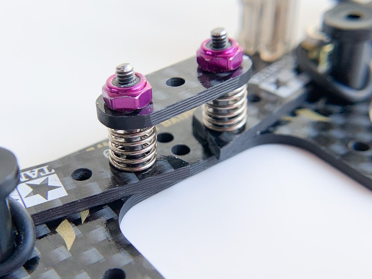
connecting plate, main shafts, silver coils, nuts
コネクトプレート、メインシャフト、銀バネ、ナット
postscript
The roller width changes when the shaft hole wears, but with 2STEP EVO, eyelets are crimped into the shaft hole to improve wear resistance. Please refer to 2STEP EVO for eyelet conversion of shaft holes.
追記
軸穴が摩耗するとローラー幅が変わりますが、2STEP EVOでは軸穴にハトメをカシメて耐摩耗性を改善しました。軸穴ハトメ化は2STEP EVOをご覧ください。↓


temporary assy
仮組み


hook the o-ring. temporary assembly
Oリング装着(仮)

roller mounting. temporary
ローラー仮組み

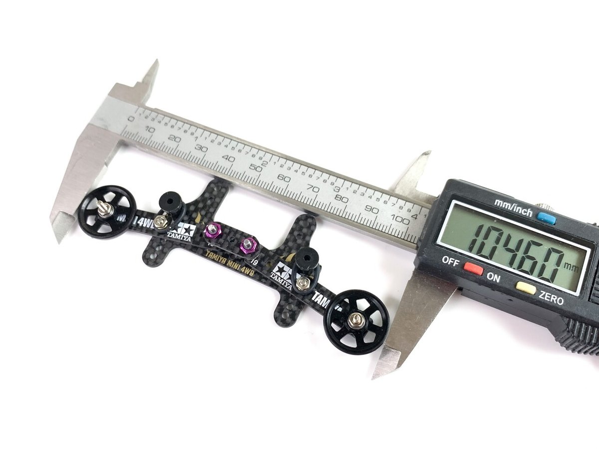
Check the roller width with a caliper
It was about 101.3 mm. It's too narrow. Since we want to operate at about 104.5 mm this time, offset the roller hole to the outside by 1.6 mm on one side.
Since the existing hole is 2.0 mm, we will expand it to a long hole of 3.6 mm while measuring with a caliper.
offset calculation
104.5 - 101.3 = 3.2 mm
3.2 ÷ 2 = 1.6 mm
1.6 + 2 = 3.6 mm
Use a slim bit of about 1.5 mm or a slim round file to enlarge it to a 3.6 mm hole. Please spread it outside!
The same is true for 13mm rollers. Offset outwards in the same way.

ノギスでローラー幅をチェック。
ノギスは幅や穴の大きさを測るのに必要な道具です。ブランド品の高級ノギスは当製作に必要ありませんが、1/100mmを測れる程度の金属製デジタルノギスをご用意ください。3000円位で購入できます。
測定の結果リアローラー幅は約101.3mmでした。狭すぎますね。今回は104.5mm位で運用したいので、ローラー穴を片側1.6mm外側にオフセットします。
既存穴は2.0mmなので、ノギスで計りながら約3.6mmの長穴に広げてゆきます。
オフセット量の計算
104.5 - 101.3 = 3.2 mm
3.2 ÷ 2 = 1.6 mm
1.6 + 2 = 3.6 mm
1.5mm位の細いビットや細い丸ヤスリで3.6mm穴に拡大しましょう。必ず外側に広げてくださいね!笑
13mmローラーの場合も同様です。同じ要領で外側にオフセットしましょう。上記19mmの場合のようにオフセット量を計算して作業を進めてください。

After widening the holes, fill the existing holes with glue.
穴を広げた後は既存の穴を瞬着で埋める予定です。
6.roller hole processing / ローラー穴加工

Re-disassemble to change hole position
穴位置を変更するので再分解してください。
Let's process it into an elliptical hole with a diameter of 3.6 mm. Please note that if you spread it too much, it will not fit in the vehicle inspection box. Spread it little by little while measuring with a caliper.
それでは3.6mmの長穴に加工します。広げ過ぎると車検BOXに収まらないので注意です。ノギスで穴径を計りながら少しずつ広げてゆきます。
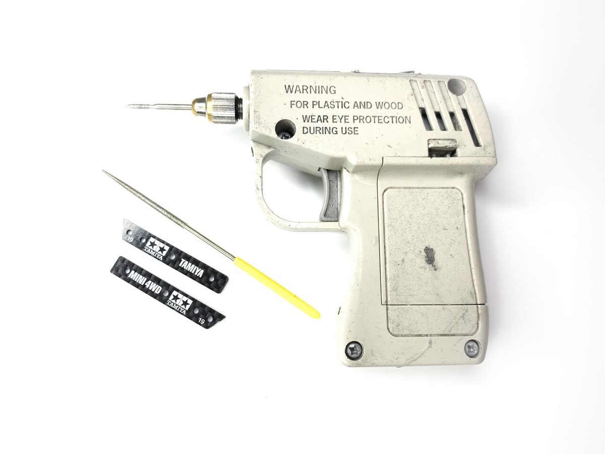
slim bit or slim file. I love Tamiya tools😻
細ビットか棒ヤスリでどうぞ。
またまた登場神リューター!
名機タミヤリューター。単3電池2本仕様。使い古したネオチャンプで動きます。電池が垂れるといい感じでゆっくり回って削り過ぎないから手仕事のような微調整ができてサイコー!でもしっかりトルクがあります。丸ノコビットを使うようなカーボン板の切断はちょっと苦手。モバイル性抜群。


from the left / glue hardener, pin📌, glues
アルテコ、ピン📌、瞬着
アルテコは瞬着硬化促進剤。ホムセン等でどうぞ。

spray just before gluing. bad smell🤮
接着直前に毎回スプレー。

Apply glue to the tip of the pin to close the hole. Spray the glue hardener after each glue application.
ピン先端に瞬着を塗って穴を塞いでゆきます。
接着剤を塗布する度に瞬着硬化剤をスプレー。

it went well. clean the hole with a Φ2.0 drill.
いい感じですね。Φ2.0ドリルで穴を掃除します。

NACHI 2.0mm
ここで登場神ドリル!
ナチと読みます。100円ドリルとは別格です。
タミヤのボックスレンチに差し込んで使います。
一本あると便利ですよー。確か500円位だったかなぁ…

Kitchen knife sharpener grindstone.
File with water. Scrape off excess glue.
Prevents the rear rollers from tilting.
100円ショップの包丁研ぎ砥石を用意。面出しします。
カーボンに水をかけながら水研ぎして、盛り上がった余分な接着剤を削り落とします。軽くシコシコすると勝手に剥がれてゆきます。リアローラーが傾くのを防ぐために行います。


temporary assembly again
再仮組み。
error 1 / 10mm. well it's OK. Let's praise😂
俺氏グッジョブ✅
7. roller angle adjustment / スラスト調整

Affix a strong double-sided tape the polycarbonate scraps in the blue portion.
強力両面テープで青色部分にポリカを貼ります。

cut the excess part with a knife.
It changes to a negative angle of about -1 degree.
as you like...
You can fine-tune the roller angle by thinly scraping the polycarbonate with a leutor after pasting the polycarbonate.
余分な部分はデザインナイフでカット。
マイナス1度前後のアッパースラストに変化します。
お好みでどうぞ。
ポリカを貼った後にポリカをリューターで薄く削るとスラストアングルの微調整ができます。
-.-.-.-.-.-.-.-.-.-.-.-.-.-.-.-.-.-.-.-.-.-.-.-.-.-.-.-.-.-.

Postscript
Polycarbonate is easy to peel off. Also, if you stick polycarbonate in that position, an unnecessary roller angle will be generated in the roll direction, which is not very good.
Put some super glue on the back of the bumper. Apply to 2 places as shown in the photo. Make fine adjustments by increasing the thickness or scraping a little.
追記
ポリカは剥がれ易いです。あとあの位置にポリカを貼ると、ロール方向に要らないスラストが発生してしまい、あまりよろしくありません。
バンパー裏に少し瞬着を盛ってください。写真のように2箇所に塗布します。盛ったり少し削ったりしながら微調整しましょう。
-.-.-.-.-.-.-.-.-.-.-.-.-.-.-.-.-.-.-.-.-.-.-.-.-.-.-.-.-.-.
8. roller mounting / ローラー装着
25 or 30mm cap screw
25mmか30mmのキャップスクリュー

It cracks because it is a single carbon
皿ビスはご遠慮ください。
カーボン一枚なので割れてしまいます。

low head processing
是非低頭処理を。リューターで回しながらヤスります。

single carbon is almost never broken when using a washer.
ワッシャー推奨。シングルカーボンでもまず割れないと思いますよ〜

Finished ✅
9. bumper slider / スライダー

Use the scraps left over when making the connecting plate.
コネクトプレートを作った時の端材を使います。

Cut the carbon scrap to an appropriate size on the blue part and attach it with strong double-sided tape.
Do not use glue. It will come off after 3 laps. Be sure to use strong double-sided tape.
いわゆる引っ掛かり防止ですね。カーボン端材を適度な大きさにカットし、強力両面テープで青色部分に貼りつけます。
瞬着ダメー🙅♂️。3周で剥がれます。強力両面テープで。

Drilling a φ6.5 hole is relatively difficult, so try cutting it with a leutor and a diamond bit of about 5 to 6 mm.
ドリルを使ったφ6.5の穴開けは割と難しいので、リューターと5〜6mm位のダイヤモンドビットで削ってみてください。大体でOKですよ。

NITTO 5015 / 20mm x 20m
神両面テープ!NITTO 5015
カーボンやポリカを貼ったり、ピンクブレーキに貼って接着力をUPさせたり、PPホイールとタイヤの接着に使ったり、何かと超便利な薄型強力両面テープ。400円位です。


Finished ✅

If the slider is moved too close to the main plate, the arm will not slide back and may cause malfunction.
スライダーをメインプレート側に寄せすぎた場合はアームがバックスライドしなくなり、作動不良の原因になります。少し隙間を開けてください。
10. finish assembly / 本組み

please loosen
緩めてください


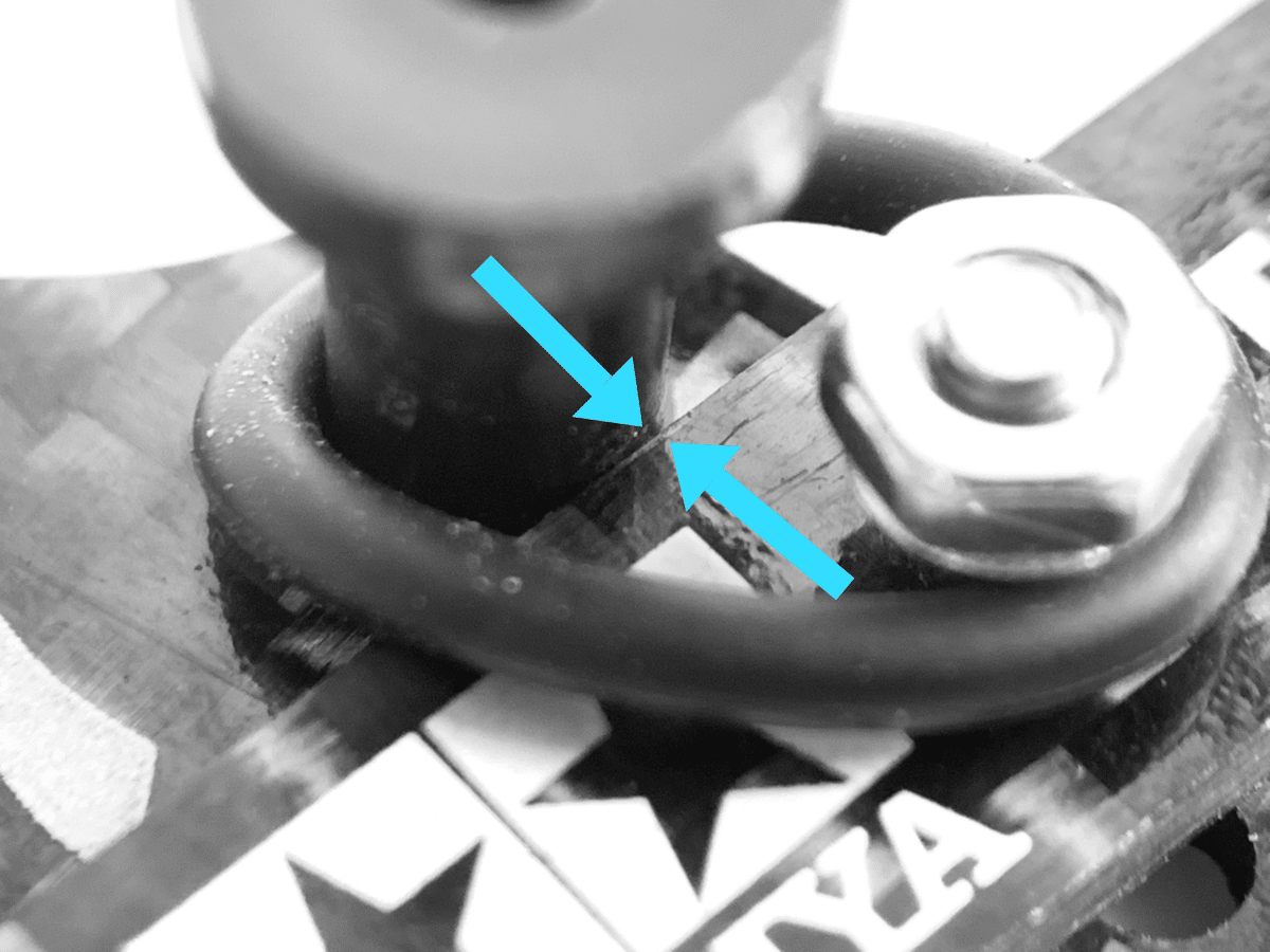
While pulling the roller lightly backward (without the stopper), tighten the screw so that the O-ring is caught under the wheel bush.
(ストッパーが付いていない状態で) ローラーを後方に軽く引っ張りながら、ホイールブッシュの下にOリングが挟まるようにビスを締め込みます。ちょっとコツが要ります。

👆The trick is to hook the O-ring shallowly. However, tighten the wheel bush screws firmly so that they do not come loose.
Oリングは浅く引っ掛けるのがコツ。でもホイールブッシュのビスは緩まないようにしっかり締め込んでくださいね。
-.-.-.-.-.-.-.-.-.-.-.-.-.-.-.-.-.-.-.-.-.-.-.-.-.-.-.-.
Postscript May 2021 / 追記

I made a hook because the O-ring often comes off while running. It's easy to install because you just hook the O-ring on the hook. Please see "16.update2" below.
ブッシュに挟んでいたOリングが走行中によく外れるのでフックを作りました。Oリングをフックに引っ掛けるだけなので装着もカンタンです。下記の「16.アップデート2」をご覧ください。
-.-.-.-.-.-.-.-.-.-.-.-.-.-.-.-.-.-.-.-.-.-.-.-.-.-.-.-.
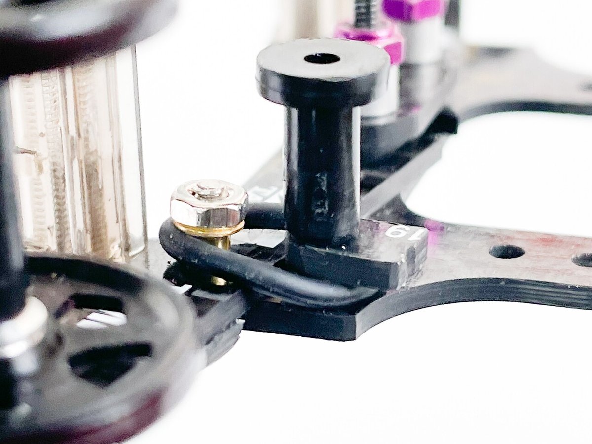
Be careful not to create a gap between the wheel bush and the bumper. The O-ring is a consumable item. Replace if there is a gap.
ホイールブッシュとバンパーの間に隙間ができないように注意してください。Oリングは消耗品です。隙間があれば交換してください。
👆Check that the O-ring is fixed with the wheel bush when the roller is lifted up. Fixing the O-ring has the effect of a return spring when moving up and down, and suppresses gimmick errors.
ローラーが上に動いた時にOリングがホイールブッシュに固定されているかチェック。このOリングの固定は上下動時のリターンスプリングの役目があり、ギミックエラーを抑えます。

glue the o-ring and eyelet
瞬着でOリングとハトメを固定
Postscript
If you apply glue, it will be troublesome to replace the O-ring, so you don't have to glue it.
追記
接着するとOリング交換が超面倒でした笑。別に接着しなくても大丈夫です。

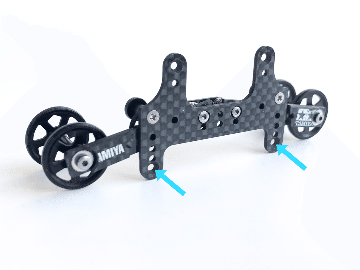
tighten the nuts until about 6.8mm
約6.5mmまでナットを締め込みます

Almost completed ✅
ほぼ完!お疲れっすー
11.stoppers & set up / ストッパー&セッティング
[standard type] 標準タイプ

GUP 15520


2mm TAP if possible
M2タップ推奨。


This is the standard type. If you set the stopper as shown in the picture, you are good at running softly as a whole. You can get a sublime landing. Standard type is God landing. The cornering is also soft.
When the stopper is set up as shown in the photo, the roller is pushed by centrifugal force during cornering and the rear roller width is narrowed by about 1.2mm.
As a result, it often does not fly straight. In that case, change the width of the front roller and make fine adjustments.
In conclusion, adjust so that the width of the front roller is narrow.
Dimensions such as chassis, bumpers, rollers and brake plates are assumed to be in perfect condition.

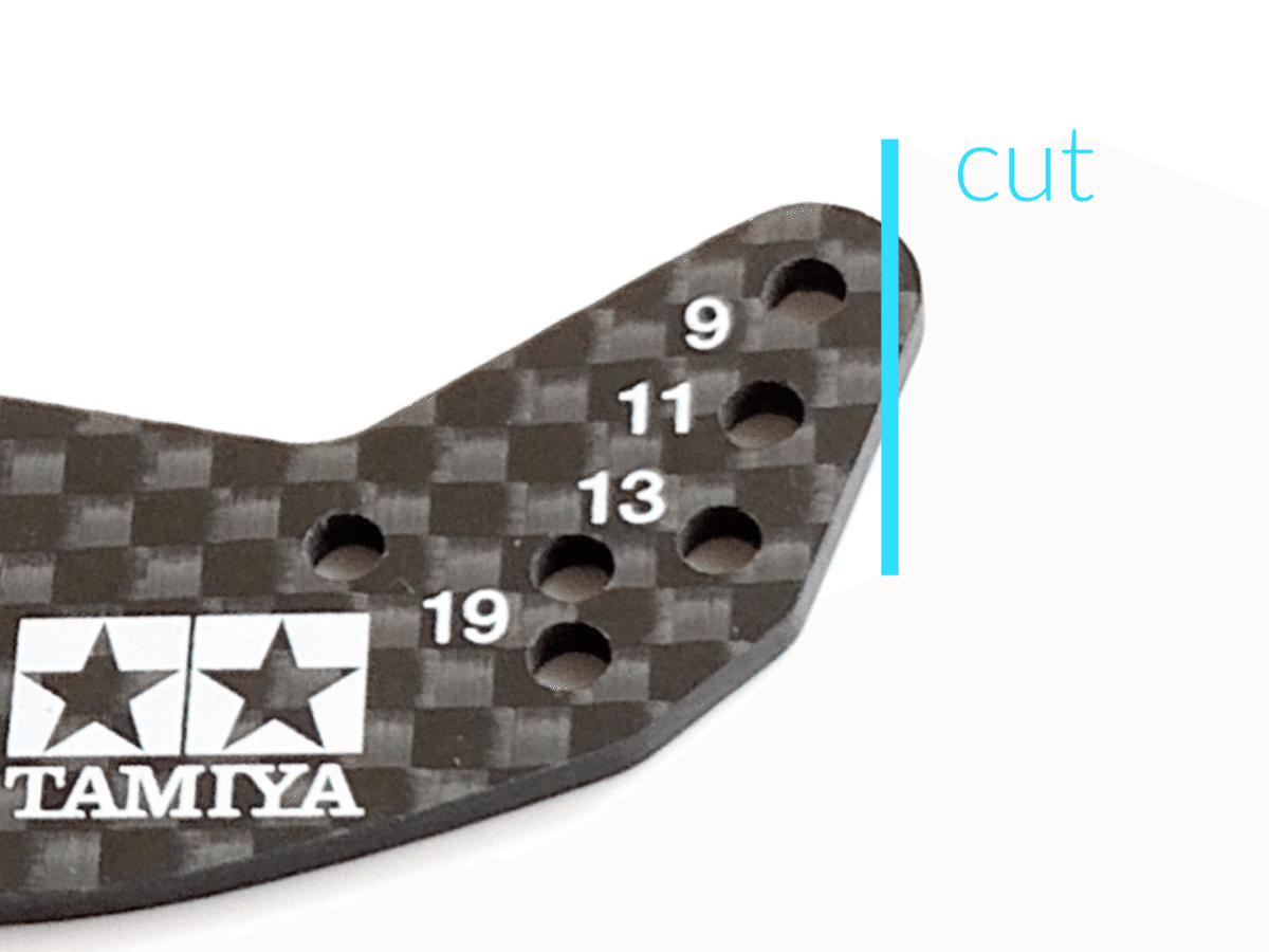
For example, mount a 9mm roller in the 11mm roller hole, mount a 9mm roller in the 13mm roller hole, or mount a 17mm roller in the 19mm roller hole. And 11mm rollers can be used in the 13mm roller holes.
The appropriate roller width for jumping from side to side without distortion depends on the roller base and cornering escape velocity, so it is case by case.

From the slope immediately after the corner, look for a test course with 3-4 straight lines, release the brakes as much as possible, check if you jump straight, and fine-tune the front roller width.
If you change the roller hole, the carbon bumper may slightly touch the fence and disturb the jumping posture. Please be careful.

こちらが標準タイプ。写真のようにストッパーを立てた場合は全体的に柔らかい走り方が得意です。崇高な着地をGETできますよ笑。標準タイプ=神着地。コーナリングも柔らかいです。
実は製作当初の初試走前は、ある程度のコーナー減速を覚悟していましたが、カーブ中盤あたりから車速が微妙に伸びる印象がありまして、一概にロスが大きいとも言えず、なかなか不思議なギミックです。
で、ここから本題です。コーナリング中は遠心力でローラーが押されてリアローラー幅は約1.2mm狭くなります。(柔らかい着地を実現するために必要な可動量です)
これにより真っ直ぐ飛ばない場合があるかも知れません。その時はフロントローラー幅を変更してみてください(フロントローラー幅を狭くする方向で調整)。広くなることは多分ありません。
例えば11mmローラー穴に9mmローラーを装着したり、13mmローラー穴に9mmローラーを装着したり、19mmローラー穴に17mmローラーを装着する、という感じです。13mmローラー穴に11mmローラーでもOKです。
シャーシ類のディメンションはパーフェクトな状態と仮定して(前後バンパーの水平度、前後ローラーの垂直度、リアブレーキプレートの水平度、車軸やホイール、タイヤのブレなどは問題ないと仮定して)ご説明しています。
左右に曲がることなくまっすぐジャンプするために適切なローラー幅はローラーベースとコーナリング脱出速度によっても変化するのでケースバイケースです。

コーナー直後のスロープから3-4枚位の直線があるテストコースを探してみてください。タミヤテープ等でブレーキを隠して前後ブレーキの効きを出来る限り弱くして、まっすぐジャンプするか目視でチェック。まっすぐジャンプしない場合はフロントローラー幅を微調整しましょう。
何もしなくても真っ直ぐにジャンプするなら調整は必要ありません。

ローラー穴を変えた場合はフェンスとカーボンバンパーが微妙に接触してジャンプ姿勢を乱すことが多々あります。ご注意ください。
[half fixed type] ハーフロックタイプ

GUP 15412


If you put up this stopper, you are good at sharp and hard running.
When traveling on a flat surface, the gimmick is almost fixed and there is no backslide due to centrifugal force during cornering, so adjustment of the front roller may be almost unnecessary.
It is locked during normal times and operates up and down and backslide only when landing. It can be said that it is the original appearance of a 2-step anchor. There is a feeling that everything started from here.
The cornering is sharp and the slope immediately after the curve is easy to jump straight, but landing is a little more difficult than the standard type. Simply put, it's close to a gimmickless bumper.
Please choose each stopper as you like. I like the combination of bumpers that have high chassis rigidity and move softly, so I like the standard type stopper.
こちらのストッパーを立てた場合はシャープで固い走りが得意です。平面走行時はギミックがほぼ固定されコーナリング中の遠心力によるバックスライドが無くなるので、フロントローラーの調整はほとんど必要ないかもしれませんね。
通常はロックしていて、着地の時だけ上下及びバックスライドします。これは2ステアンカーの原点ですねー。
コーナリングにキレがあり、カーブ直後のスロープもまっすぐ飛ばし易いのですが、前者よりも着地は少し難しくなります。簡単に言えばギミックレスバンパーに近いです。
[BECK type]

φ4.0 spacer
Postscript
A stopper like the one in the picture is also recommended. I am good at landing with high reproducibility. It's a really great landing.
The backslide amount of the arm is the largest of the three. Please choose each stopper as you like.
追記
写真のストッパーもおすすめ。再現性の高い着地が得意です。本当に素晴らしい着地です。
アームのバックスライド量は3つの中で最大になります。
各ストッパーはお好みで選んでください🔥🔥🔥
12.complete✅


2step anchor completed ✅
13.maintenance / メンテナンス
dent is visible.
打痕があります
For race use, replace the wheel bush and O-ring before the race. Even for everyday use, it is recommended to check the wheel bush for damage frequently.
After running for a day, turn the wheel bush about 1/4 turn and it will last 4 times longer.
レースユーズならホイールブッシュとOリングはレース前に交換しましょう。普段使いの場合でも、ホイールブッシュの損傷をこまめに点検することをお勧めします。
1日走ったらホイールブッシュを1/4回転位クルッと回すと4倍長持ちします。
14.special thanks!!
testers / テスターの皆様
🅾️gℹ️様
トイズきゃっぷ店主様 / Toy’s cap boss
Genki Konishi様
GPS様
Hitoshi様
ᴮᴱᶜᴷ @月花楼
sponsors / サポートして頂いた皆様
まさふみ様
Zoro様
Zy_System様
まさ様
くり様
anny198*****様
exodus198*****様
Condorman様
ブーメランパンツ10様
15. update1 / アップデート1
Postscript May 2021
In the case of silver coil, it was difficult to adjust the hardness, so I added an O-ring version. Fine adjustment of vertical movement has become easier.
But if you like coils, please use coils. Please choose the one you like💁♂️
追記
銀バネは固さ調整が難しかったのでOリング版を追加しました。上下動の微調整がカンタンになりました。
ですがバネ派の方は銀バネでも構いません。お好きな方でどうぞ!

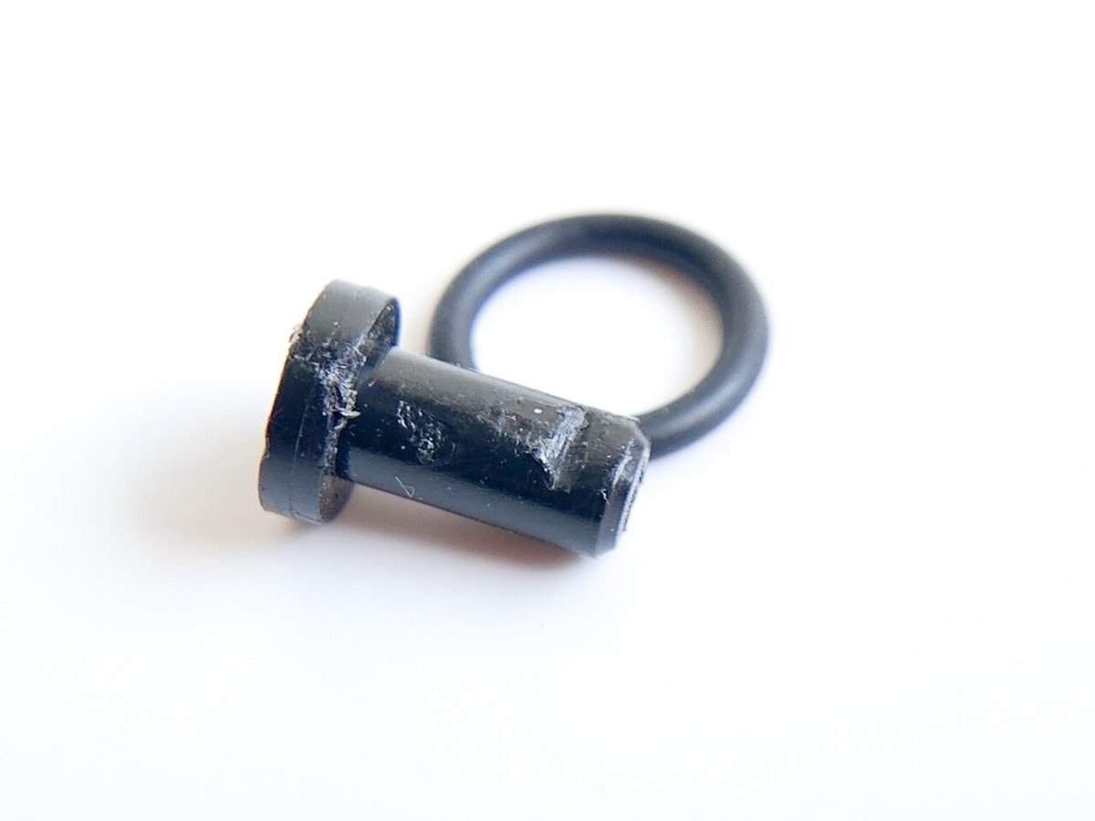
Please prepare an O-ring and a spacer.
Oリングとスペーサーをご用意ください。

Remove the silver coil
銀バネを外します

Hook the O-ring on the main shaft.
メインシャフトにOリングを引っ掛けます


Install the connecting plate
コネクトプレートを取り付けます

Install the spacer and lightly tighten the nut.
スペーサー取り付けて、軽くナットを締め付けます

Use the O-ring by crushing it a little. Adjust the hardness to your liking.
Oリングを軽く潰して使用します。お好みの固さに調整してください。

Update✅
16. update2 / アップデート2

Postscript May 2021
Make a hook to hook the O-ring with carbon or FRP scraps. The point is to finish with the same curve as the aluminum spacer.
Please install it as it will improve the behavior.
追記
端材を利用してOリングを引っ掛けるフックを作ってください。アルミスペーサーと同じアールで仕上げるのがポイントです。
動作や挙動が良くなるので是非インストールしてください。
Postscript
If there is a step between the carbon hook and the wheel bush or aluminum spacer, it will be caught by vertical movement and may cause malfunction.
If the round radius of the carbon hook is large, scrape it little by little, referring to the outer diameter round of the aluminum spacer.
If the carbon hook is scraped too much and gets caught, place glue on the carbon hook to inflate it and shape it so that it does not form a step.
追記
カーボンフックとホイールブッシュやアルミスペーサーに段差が出来ると上下動で引っ掛かってしまい作動不良の原因になります。
フックのラウンドアール径が大きい場合は、アルミスペーサーの外径アールを参考にして少しずつ削ります。
逆にカーボンフックを削りすぎて引っ掛かる場合は、カーボンフックに瞬着を盛り付けて少し膨らませ、段差にならないように造形してください。


countersunk screw / 皿ビス

t1.5mm spacer / 1.5mmスペーサー

hook / フック

wheel bush / ブッシュ

Updated✅
-.-.-.-.-.-.-.-.-.-.-.-.-.-.-.-.-.-.-.-.-.-.-.-.-.-.-.-.-.-.-
Thank you for watching!
I would be happy if you could tap the ♡ mark at the bottom right.
See you again 👋 BECK JPN
ご視聴ありがとうございます。
右下の♡ボタンをTAPしてもらえると喜びます。
ではまた!
Related article 💁♂️関連記事 バクスラアンカー
Backslide anchor system 1
Backslide anchor system 2
Backslide anchor system 3
Backslide anchor system 4
Paid tutorial 💁♂️有料マニュアル
That’s Japanese articles. SLY🙏
Bフレキ / MS suspension
ミニピボット / mini pivot
Feel free to follow me✨
instagram.com/beck.jpn
twitter.com/beckjpn_
YouTube
youtube.com/c/BECKJPN
この記事が気に入ったらサポートをしてみませんか?