
パンフレットスペックからモデルを作ってみよう! 「方向制御バルブ」

今回モデル化にチャレンジする方向制御バルブ
前回作成した不二越さんの油圧ポンプとモータに引き続き、今回は不二越さん(株式会社不二越)の方向制御バルブ(SS-G03-C7Y-GR-D2-J22)のモデリングにチャレンジしてみます。
パンフレットにはさまざまな情報が掲載されています。今回作成するモデルは図1のタイプの方向制御弁にします。このタイプは「C7Y」となり、最大流量を100[L/min]流したいので「G03」のDCソレノイドタイプを選ぶことになります。また、この仕様設定ですと耐圧は25[MPa]となります。
このタイプのバルブ開口圧損はパンフレットの仕様値から80[L/min]で約1.3[MPa]なので、オープン時の開口面積を0.345[cm^2]としました。
応答時間はソレノイドONで0.06~0.09[s]、スプリングリターンが0.03~0.05[s]と記載があります。ソレノイドのON/OFFで応答性が違うのですが、モデル化は時定数0.075[s]の一次遅れ応答を共通で使うことにします。パンフレットに記載されている応答時間は最大応答時間だと思うので、一次遅れで時定数0.075[s]だと実際より遅いかもしれません。

あと図1について少し説明をしておきます。バルブポジションは3つあり、ソレノイドのON/OFFでポジションを切り替えます。ソレノイドは「a」と「b」の2つがあり、「a」をONするとPポートとAポート、そしてBポートとTポートがつながります。「b」をONするとPポートとBポート、そしてAポートとTポートがつながります。「a」も「b」もOFFの場合にはPポートがTポートにつながり、AポートとBポートはどこにも接続されません。ちなみに「a」も「b」もONというのは基本してはなりませんが、もしした場合はバルブの仕様によりますがたぶん釣り合ってどちらもOFFと同じになると思います。
おまけの情報ですが、今回の図は「a」のソレノイドをONにすると電磁石がONになってスプールが引き抜かれるために図の左側のポジションになり、「b」をONにすると右側のポジションになります。ソレノイドの引く抜くということに忠実な図となっています。しかし油圧パイロットの場合と同じように、スプールを押すイメージで表現されている場合もあります。その場合には「a」と「b」が逆になっている場合もありますのでバルブの仕様情報をよく見ておくとよいでしょうね。
MapleSimでモデル化
最初にモデル最終形を図2に示します。
バルブは5つの可変オリフィスブロック、「a」「b」2つのソレノイド入力に応じた開口面積を算出する「Lokkup Table 1D」ブロック、応答性を模擬した「First Order」ブロックから構成されています。
可変オリフィスブロックの設定はデフォルトのままです。「First Order」ブロックの設定は時定数を0.075[s]にしています。
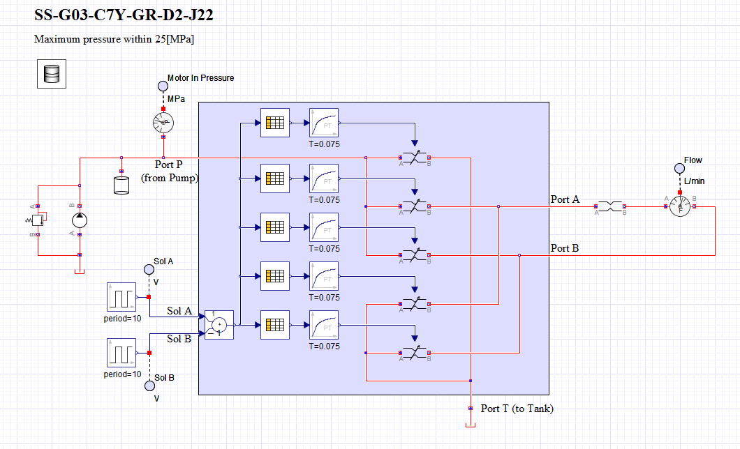
「Lokkup Table 1D」ブロックの設定の前に、入力であるソレノイド電圧について説明します。ソレノイドA側の電圧をプラス、ソレノイドB側の電圧をマイナスと定義してその差分を「Lokkup Table 1D」ブロックに入力しています。これによってどちらの電圧がONになったかを正負の符号で判断できるのです。そして、もし両方ONになっても差分は0になるので中立のままになります。
図3から図5に「Lokkup Table 1D」ブロックの設定であるソレノイド電圧に対応する開口面積の値を記載しています。このバルブは基本、ON/OFFで使われますので、0[V]か24[V]だけ考えればよいのですが、実際には中間域が存在します。ON/OFFの動作するバルブの場合、この中間域はとても短くなっていますし、ピーク圧がたたないような完全閉塞をしないような工夫などいろいろな工夫がされています。まぁON/OFFで使っている分には、モデルではあまり気にする必要はありません。今回のモデルでは10[v]から15[V]で切り替わるように設定しました。図3のPからTへのラインは中立位置で開口を開けています。図4は「a」側のソレノイドがONの場合に、PからAへの開口とBからTへの戻りの開口が開くようにしています。逆に「b」側のソレノイドがONの場合にはPからAへの開口もBからTへの戻りの開口もゼロ、要するに閉じていることを表しています。図5は「b」側のソレノイドがONの場合に、PからBへの開口とAからTへの戻りの開口が開くようにしています。逆に「a」側のソレノイドがONの場合にはPからBへの開口もAからTへの戻りの開口もゼロ、要するに閉じていることを表しています。


シミュレーションをしてみよう
シミュレーション結果を図6に示します。
図6の1番上がバルブからの流量です。A側から出ている場合はプラス、Bから出ている場合にはマイナスになっています。2番目はバルブへの入力側の圧力です。3番目は2つのソレノイド「a」「b」の電圧を表しています。
「a」側のソレノイドがONになるとA側のポートから油が出て、「b」側のソレノイドがONになるとB側のポートから油が出ていることがわかります。「a」と「b」の切り替え時には中立を通過するのでバルブへの入力圧が一旦
下がっていることがわかります。
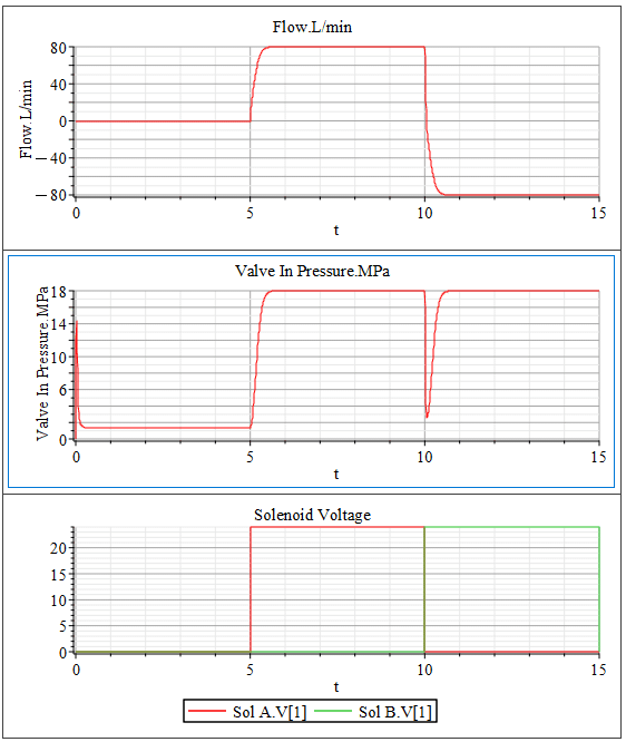
ON/OFFではありますが、このバルブを使うことで油の流れる方向を変えることができますので、例えばモータの回転方向を変えることができるようになります。
【English】
Following the hydraulic pump and motor created in the previous issue, we will now try modeling a directional control valve (SS-G03-C7Y-GR-D2-J22) from NACHI, Ltd.
The product pamphlet contains a wide range of information. The model we will make will be a directional control valve of the type shown in Figure 1. This type is "C7Y," and since we want the maximum flow rate to be 100[L/min], we will choose the "G03" DC solenoid type. Also, with this specification setting, the withstand pressure will be 25[MPa].
Since the valve opening pressure drop of this type is approximately 1.3 [MPa] at 80 [L/min] based on the specification values in the pamphlet, we assumed an opening area of 0.345 [cm^2] when open. Response time is listed as 0.06-0.09[s] for solenoid ON and 0.03-0.05[s] for spring return. Although the response is different with the solenoid ON/OFF, we will use a common first-order delay response with a time constant of 0.075[s] for modeling. I think the response time listed in the pamphlet is the maximum response time, so a first-order delay with a time constant of 0.075[s] may be slower than the actual response time.
I'll also explain a little about Figure 1. There are three valve positions, and the position is switched by turning the solenoid on and off. There are two solenoids, "a" and "b." When "a" is turned on, the P port is connected to the A port, and the B port is connected to the T port. When "b" is turned on, P port, B port, A port, and T port are connected. When both "a" and "b" are off, the P port is connected to the T port, and the A and B ports are not connected anywhere. Note that both "a" and "b" should not be turned on, but if they are, depending on the valve specifications, they will probably balance each other out and both will be the same as if they were off.
As an extra piece of information, this time the diagram shows that when the "a" solenoid is turned on, the electromagnet is turned on and the spool is pulled out, resulting in the position on the left side of the diagram, and when the "b" solenoid is turned on, the position on the right side. The diagram is faithful to the solenoid's pulling out. However, as in the case of a hydraulic pilot, it may be represented as a pushing image. In such cases, "a" and "b" may be reversed, so it is advisable to look carefully at the specification information of the valve.
Modeling with MapleSim
First of all, the complete model is shown in Figure 2.
The valve consists of five variable orifice blocks, a "Lokkup Table 1D" block that calculates the opening area according to the two "a" and "b" solenoid inputs, and a "First Order" block that simulates response.
The variable orifice block settings are left at default. The "First Order" block is set with a time constant of 0.075[s].
Before explaining the settings of the "Lokkup Table 1D" block, I will explain the input solenoid voltages. The voltage on the solenoid A side is defined as positive and the voltage on the solenoid B side as negative, and the difference between the two is input to the "Lokkup Table 1D" block. This allows us to determine which voltage is turned ON by the sign of positive or negative. And if both are turned on, the difference will be zero and remain neutral.
Figures 3 to 5 show the values of the opening area corresponding to the solenoid voltage, which is the setting of the "Lokkup Table 1D" block. Since this valve is basically used in ON/OFF mode, only 0[V] or 24[V] should be considered, but in actually there is an intermediate range. In the case of valves that operate ON/OFF, this intermediate range is very short. Well, for ON/OFF use, you don't need to worry too much about the model. In this model, I set it to switch from 10[v] to 15[V]. The line from P to T in Figure 3 has an opening at the neutral position. Figure 4 shows that when the solenoid on the "a" side is ON, the opening from P to A and the opening from B to T return are open. Conversely, when the solenoid on the "b" side is ON, both the opening from P to A and the opening from B to T are zero, in other words, closed. Figure 5 shows that when the solenoid on the "b" side is ON, the openings from P to B and from A to T are open. Conversely, when the solenoid on the "a" side is ON, both the opening from P to B and the opening from A to T are zero, in other words, closed.
Let's run a simulation
Simulation results are shown in Figure 6.
The top of Figure 6 shows the flow rate from the valve, positive if it comes out of side "A" and negative if it comes out of side "B." The second shows the pressure on the input side to the valve, and the third shows the voltage across the two solenoids, "a" and "b. You can see that when the solenoid on the "a" side is turned on, oil comes out of port "A" and when the solenoid on the "b" side is turned on, oil comes out of port "B". When switching between "a" and "b," you can see that the input pressure to the valve is temporarily lowered because it passes through neutral.
Although ON/OFF, this valve can be used to change the direction of oil flow so that, for example, the direction of motor rotation can be changed.
【Sample】
Created by MapleSim 2023
この記事が気に入ったらサポートをしてみませんか?