
パンフレットスペックからモデルを作ってみよう! 「油圧モータ」

今回モデル化にチャレンジする油圧モータ
前回作成した不二越さんの油圧ポンプに引き続き、今回は不二越さん(株式会社不二越)の油圧モータ(PHV-1B)のモデリングにチャレンジしてみます。今回、入手できたのはWEBページに掲載されている情報のみだったので、前回のポンプモデルより情報は少なめです。
今回のモデル化に使う情報は、モータの最大容量458.3[cc/rev]とHi-Loの変速ができることだけです。1速(Lo側)は最大容量だとして、2速(Hi側)変速時の容量はWEB情報からはわかりませんでした。変速は外部からのパイロット圧によって切り替えるようです。このパイロット圧力の条件もWEBからは判断できなかったので、今回は切り替え信号でHi-Lo切り替えられるようにすることにします。なお、2速時のモータ容量は勝手に300[cc/rev]とします。
なお、最高圧が24.5[MPa]という記述があるので、リリーフ圧を気持ち安全目に24[MPa]に設定しておくことにします。前回作成したポンプの最高圧は28[MPa]でしたが、それぞれの油圧機器の耐圧に合わせたシステム設計をしないとなりません。共通のリリーフバルブで耐圧をカバーする場合には、最も低い(弱い)機器に合わせなければなりません。
MapleSimでモデル化
今回のモデル化の立ち位置は前回のポンプ同様に、油圧機器を組み合わせた油圧システム全体の挙動を見たいという立ち位置で作成していきます。要するに今回の場合、モータへ圧力がかかることによりモータに接続される回転体へ回転力として伝えること、そしてその回転数からモータを通過する流量がわかればよいというスタンスでモデル化を行います。なので、モータに含まれる細かい油圧機器のモデル化は行いません。
さて、モデル化の本題ですが、最初にモデル最終形を図1に示します。ポンプに比べるとかなりシンプルですね。効率計算もトルク計算もないからです。ちなみに今回使うブロックは、自分で作成しなくても効率やトルク計算をブロック自体がしてくれるので、あえて自分で作らなくてよいのです。
「えっ?ポンプも同じようなブロックないのかって?」
すみません。
同じようにあえて効率とかトルクとか自分でも作らなくても数値を入れるだけのブロックが実は用意されています。それを使えばもっと簡単にできましたね。
まぁ、MapleSimの勉強的な記事なのでいろいろな方法を説明するためと思ってお許しください。
逆にですが、モータの方は前回のポンプのようなブロックはありません。それはモータはそもそも回転軸が必要なので、どれだけモータを通過させたかだけだと意味がないから、そんなブロックは存在していないんですね。
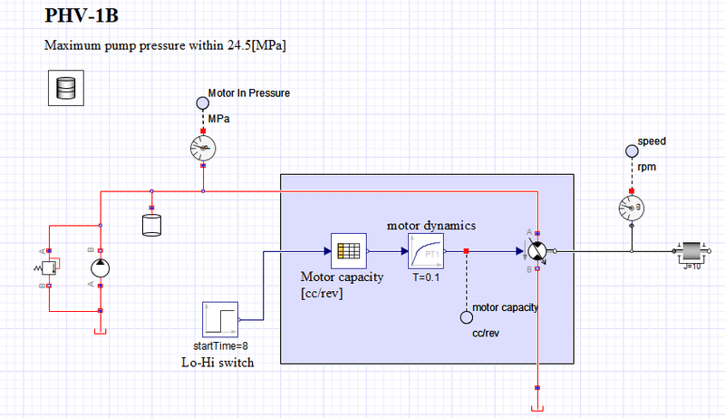
図1を見ると、背景色を変えている部分はモータ部分のモデルです。
それ以外はモータモデルを動かすための部分なので、詳しくは説明しませんが、ざっと説明しておくと。左側の赤いラインの方はモータへ送る作動油をポンプによって表現している部分です。モータへは圧力として作用させたいのでチャンバーを付けています。また、モータの最高使用圧が24.5[MPa]ということで、24[MPa]でリリーフするリリーフバルブを設置しています。同じく左側の黒いラインの方はモータHi-Loを切り替える信号をステップ応答ブロックで作りました。最初は「0」で8[s]以降「1」を出力します。なお、「0」のときLo(458.3[cc])、「1」のときHi(300[cc])としています。
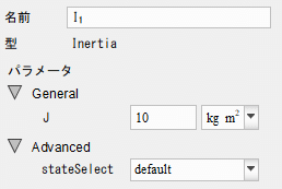
モータ部分のモデルの右側はモータが回す回転体「Inertia」を付けています。「Inertia」ブロックと「Inertia」の回転数を見るためにセンサーブロックを付けています。「Inertia」の設定は図2のように慣性質量J=10[kgm^2]と設定しました。それ以外の設定はデフォルトのままです。
さて、モータモデル本体部分の説明をします。
と言っても今回はちょっぴりだけしかモデル化していませんけど、、、
設定するところが一か所だけです。
モータ容量を外部から設定できるようにするために、図3に示すように、「Use variable displacement」にチェックを入れるだけです。Dmaxの値が458.3[cm^3]になっていますが、チェックが付いていると外部入力に従うので、Dmaxは無効になります。
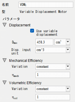
なお、先に言いましたが今回は効率は一切入れてません。
効率を入れたい場合には、機械効率なら「Mechanical Efficiency」の設定、容積効率なら「Volumetric Efficiency」を設定するとよいでしょう。図の表示では一定値ですが、いろいろと設定できるようです。
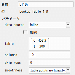
モータの容量は外部入力にしましたので、その部分を「Lookup Table 1D」と一次遅れブロックで作成しました。
「Lookup Table 1D」の設定を図4の「table」設定部分のように設定します。「0」のとき458.3[cc]となり、「1」のときに300[cc]を出力します。
今回のモデルでは「Lookup Table 1D」の入力が「0」と「1」の2値という前提で作っています。「0」と「1」の間の数字でも、「0」未満や「1」を超える数字でも線形補間して数字が出てしまうので、使う際にはそのことを気を付けて使いましょう。
続いて一次遅れブロックの設定は時定数設定Tを0.1[s]としただけです。
最後に作動油の設定(ドラム缶のアイコン)ですが、体積弾性率Kは14000[bar]だとエラーになるので8000[bar]に変更しました。他の油圧システムを作った記事でもシステムがちょっとでも複雑になってくると体積弾性率は大きいとエラーになってデフォルト8000[bar]にしました。
このあたり、MapleSimのプロなら理由や対処がわかるのかもしれませんが、そのあたりは私は詳しくないので、油圧システム側がそこそこの動きをしているということで、ここではかなりやわらかめの油ですが体積弾性率を8000[bar]として先に進みます。
シミュレーションをしてみよう
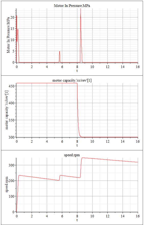
シミュレーション結果を図5に示します。
図5の1地番上がモータへの入力圧力です。なお出力側はタンクブロックにつながっているので0[MPa]です。2番目はモータ容量です。3番目(一番下)がモータ回転数を表しています。
モータへの入力圧力を見ると、モータが低回転のときは圧力が高くなっています。モータ通過流量がポンプが吐き出す流量に釣り合うまでは圧力が高くなって、モータに接続された回転体「Inertia」の回転を加速させる側に働いているのがわかります。回転数が速くなるとモータ通過流量がポンプが吐き出す流量を超えてしまい負圧になっています。図5のモータへの入力圧力は一見するとゼロのように見えますが、わずかにゼロを下回って負圧になっています。そのため図5の3番目のモータ回転数を見ると二百数十回転まで上がったあとは200[rpm]くらいまで徐々に回転数を下げていき、またモータ通過流量がポンプが吐き出す流量を下回っている間は圧力が上がってモータ回転が上がっているのがわかります。
次に、図5の2番目のモータ容量を見ると、8[s]になるとモータ容量が小さくなっている(Hiへ変速している)のがわかります。時定数0.1[s]のダイナミクスで小さくなっています。モータ容量が小さくなりモータの1回転あたりの通過流量が減るために、より高い回転数にならないとポンプの吐出し量に釣り合いません。そのために図5のモータ回転数を見ると、Hiに変速することによって、Loよりも高い回転数になっていることがわかります。
ちなみに当然のことではありますが、Hiにすると同じ圧力での加速トルクは減少します。そのため、トルクが必要な場面ではLoにしなければなりません。
その他の気になること
最高使用回転数についての記述がWEBからは見つけられませんでしたが、実際には存在します。最高使用回転数を超えた使い方をするとモータが壊れちゃうので、シミュレーションをして、そのような使われ方がないようにしっかり確認しなければなりません。
また、今回のモデルでは油圧モータは圧力によって回される場合のみだったけど、実際の使われ方では回転軸に外力が働いて回される場合もシステムによってはありえます。そんな使われ方をしても壊れないのかモータ仕様書を見て確認しなければなりませんし、シミュレーションをして規定以内であることを確認しなければなりません。
以上2つのことが、モデル化以外で気になったことです。
【English】
Hydraulic motor to be modeled this time
Following the hydraulic pump model created in the previous issue, I will try modeling a hydraulic motor (PHV-1B) manufactured by the NACHI Corporation. This time, the information I was able to obtain was only what was posted on the web site, so there is less information than in the previous pump model.
The only information used for this modeling is the motor's maximum capacity of 458.3 [cc/rev] and the ability to shift between Hi-Lo gears. assuming 1st gear (Lo side) is the maximum capacity, I could not find the capacity for 2nd gear (Hi side) shifting from the web information. It seems that the gearshift is switched by pilot pressure from an external source. Since we could not determine the condition of this pilot pressure from the web, I decided to make it possible to switch between Hi and Lo with a switching signal this time. In addition, the motor capacity in 2nd gear is assumed to be 300 [cc/rev] on its own.
Since there is a description that the maximum pressure is 24.5[MPa], I will set the relief pressure to 24[MPa] for a feeling of safety. The maximum pressure of the pump I created last time was 28[MPa], but the system must be designed to match the withstand pressure of the respective hydraulic equipment. If a common relief valve is used to cover the pressure resistance, it must be matched to the lowest (weakest) component.
Modeling with MapleSim
As with the previous pump, this time I will model the pump from the standpoint that I want to see the behavior of the entire hydraulic system that combines the hydraulic equipment. In short, in this case, I will model the motor as if the pressure applied to the motor is transmitted as rotational force to the rotor connected to the motor, and the flow rate through the motor is known from the rotational speed of the motor. Therefore, I will not model the detailed hydraulic components included in the motor.
Now, let us discuss the main issue of modeling. First of all, the complete model is shown in Figure 1. Compared to the previous pump model, it is quite simple. This is because there are no efficiency or torque calculations. Incidentally, you don't have to make the block used this time because the block itself does the efficiency and torque calculations without you having to make them yourself.
Doesn't MapleSim have a pump block that can be used as conveniently as the motor block?
Sorry. A similar convenient pump block does exist.
In the same way, there is actually a block available where you can just put in numerical values without even daring to create your own efficiency or torque. It would have been much easier if I had used that.
Well, forgive me for thinking that this is a study article on MapleSim to explain the various methods.
On the contrary, but the motor does not have a block like the previous pump. That's because a motor needs a rotating shaft in the first place, so it doesn't make sense to just say how much you let the motor go through, so no such block exists.
If you look at Figure 1, the part that changes background color is the motor part of the model. The rest of the model is the part used to move the motor model, so I won't go into detail, but I'll give a quick explanation. The red line on the left side is the part that represents the hydraulic oil sent to the motor by the pump. A chamber is attached to the motor because I want it to act as a pressure to the motor. Also, since the maximum working pressure of the motor is 24.5 [MPa], a relief valve is placed to relieve the pressure at 24 [MPa]. The same black line on the left side is a signal to switch the motor Hi-Lo with a step response block. The signal is initially "0" and outputs "1" after 8[s]. The Lo (458.3[cc]) is set at "0" and the Hi (300[cc]) is set at "1".
On the right side of the model of the motor section is attached "Inertia," a rotating body that is turned by the motor. The "Inertia" block and a sensor block are attached to see the rotation speed of the "Inertia. Inertia mass J=10[kgm^2] is set as shown in Figure 2. Other settings are left as default.
Now, I will explain the main part of the motor model. This time, however, only a little bit is modeled, and there is only one place to set up.
To allow the motor capacity to be set externally, simply check the "Use variable displacement" checkbox, as shown in Figure 3. The value of Dmax is 458.3[cm^3], but with the checkbox checked, Dmax is disabled because it follows the external input.
As I mentioned above, I did not include any efficiency in this case. If you want to include efficiency, you can set "Mechanical Efficiency" and "Volumetric Efficiency" in Figure 3. The figure shows a constant value, but it can be set in various ways.
Since the capacity of the motor was set as an external input, that part was created with "Lookup Table 1D" and a first-order delay block. The "Lookup Table 1D" is set as shown in the "table" setting section of Figure 4. When "0" is set, the output is 458.3 [cc], and when "1" is set, the output is 300 [cc]. In this model, the "Lookup Table 1D" input is assumed to be a binary value of "0" and "1". Even numbers between "0" and "1," numbers below "0" or above "1" will be linearly interpolated to produce a number, so be careful when using this model.
The next setting for the first-order delay block is just to set the time constant T to 0.1[s].
Finally, for the hydraulic oil setting (drum icon), I changed the volume modulus K to 8000[bar] because an error occurs if the volume modulus is 14000[bar]. In the article where I made other hydraulic systems, when the system became even a little bit more complex, the volume modulus was set to the default 8000[bar] because of an error if the volume modulus was too large. I am not familiar with this MapleSim professional may know the reason and how to deal with it, but I am not familiar with that area, so I will assume that the hydraulic system is working well there, and I will go on with the volume modulus as 8000[bar], although the oil is quite soft here.
Let's run a simulation
Simulation results are shown in Figure 5.
The top of Figure 5 shows the input pressure to the motor, and the output side is 0 [MPa] since it is connected to the tank block. The output side is 0 [MPa] because it is connected to the tank block. The second part of the figure shows the motor capacity. The third (bottom) figure shows the motor speed.
Looking at the input pressure to the motor, we see that the pressure is higher when the motor is running at low RPM. Until the motor flows balance the pump flow, the pressure is higher and you can see that it is working on the side of accelerating the rotation of the rotating body "Inertia" connected to the motor. As the rotation speed increases, the motor flows exceed the pump flow, resulting in a negative pressure. The input pressure to the motor in Figure 5 appears to be zero at a glance, but it is slightly below zero, resulting in a negative pressure. Therefore, looking at the motor speed, we can see that the motor speed rises to about 230 [rpm] and then gradually decreases to about 200 [rpm], and that the pressure rises while the motor flow rate is below the pump flow rate, causing the motor speed to increase.
Next, looking at the motor capacity, we see that the motor capacity is getting smaller (shifting to Hi) at 8[s]. It is getting smaller with a time constant of 0.1[s] dynamics. Since the motor capacity becomes smaller and the flow rate per revolution of the motor decreases, it must be at a higher rpm to balance the discharge of the pump. For this reason, the motor speed in Figure 5 shows that by shifting the speed to Hi, the speed is higher than that of Lo. Incidentally, although it is a matter of course, the acceleration torque at the same pressure decreases when shifting to Hi. Therefore, Lo must be used in situations where torque is required.
Other interests
I could not find a description of the maximum limit speed from the web site, but it is supposed to exist in practice. If the motor is used in a way that exceeds the maximum speed limit, the motor will break, so we must run a simulation to make sure that such usage does not occur.
Also, in this model, the hydraulic motor is only turned by pressure, but in actual use, the motor may be turned by an external force on the rotating shaft, depending on the system. We must check the motor specifications to make sure that the motor will not break even if it is used in such a way, and we must also run simulations to make sure that the motor is within the specifications.
These are the two things I was concerned about other than modeling.
【Sample】
Created by MapleSim 2023
この記事が気に入ったらサポートをしてみませんか?