
パンフレットスペックからモデルを作ってみよう! 「作った油機モデルでポンプ・モータシステムを組んでみよう!」

今回組むポンプ・モータシステム
今回はこれまでに作ってきた不二越さん(株式会社不二越)のポンプモデル、モータモデル、そしてバルブモデルを使って、図1のような1ポンプ、2バルブ、2モータの油圧システムを作成してみたいと思います。なお、リリーフバルブはMapleSimの既存ブロックを用います。設定したリリーフ圧は油圧機器の最も弱いものに合わせて設定しました。
このようなモデリングを行うことで既製品の油圧機器を組み合わせて作った油圧システムがどのような挙動を示すのか、そしてどのような課題があるのかを実際のモノを作らずに想定することができます。

MapleSimでモデル化
モデルの最終形は図2のようになります。
これまでに作成したポンプモデル、バルブモデルを2つ、モータモデルを2つコピぺして結線するだけです。結線ラインには油圧を計算するチャンバーを付けておきます。すべての油圧機器間にチャンバーがなくても、うまいことMapleSimが判断して計算してくれる場合もありますが、私は油圧機器間のラインにはチャンバーを置くようにしています。
あとはMapleSimのリリーフバルブブロックをポンプの吐き出しラインに結線してタンクラインへ戻すだけです。
詳細な設定はこの記事の最後に添付してあるモデルを参照してみてください。

シミュレーションをしてみよう
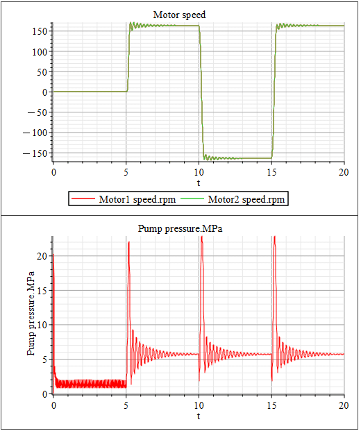
それでは作成したモデルのシミュレーションを実行してみましょう。結果は図3のようになります。
5秒で2つのバルブを開くと2つのモータ(Motor1とMotor2)が同じように回転します。10秒でバルブのスプールを逆側に動かすとモータが逆回転していることがわかります。さらに15秒で最初と同じ方向にバルブのスプールを動かすと最初と同じ方向に回転をはじめます。
2つのモータも2つのバルブもまったく同じ設定なので、まさにコピーしたように同じ動きになっていますね。現実世界ではこんな風にはなりませんけどね。
当たり前のことですが、モデルは人間が想定して設定したことしか反映されません。だから、設計者が気になることを自分自身で設定してあげる必要があります。
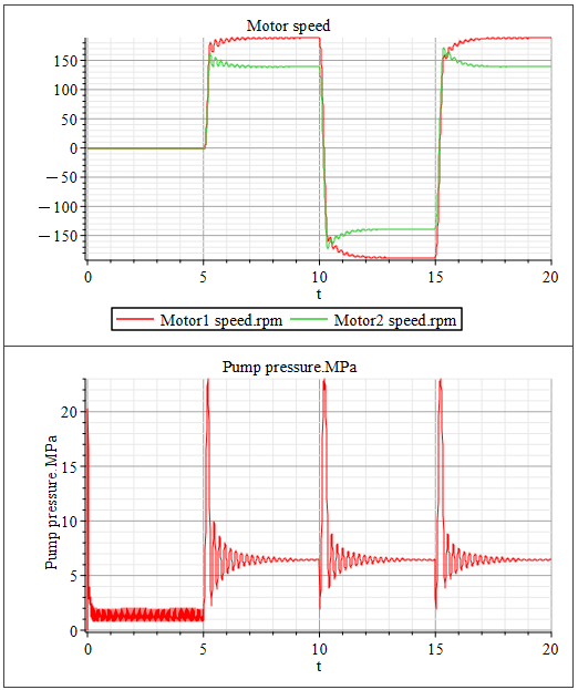
そこで、本記事では最後にMotor2の負荷を1.4倍にして、その影響を見てみることにしました。図4がその結果です。負荷が大きくなったMotor2の方の回転数がさきほどの結果に比べて低下しているのがわかりますね。一方でMotor1側の回転数が先ほどの結果よりも上昇しています。何も変えていないMotor1の回転数はなぜ上昇したのでしょうか?
それは負荷が上がって回転数が落ちたMotor2の分の流量がMotor1側に移ったからです。また、違った見方をすれば、Motor2側の負荷が上がったために、ポンプ圧が上がっていますね。そのために動力源であるポンプの圧がさきほどよりも上がったために、Motor1へ作用する力が増えてMotor1の回転数が上昇したとも見れますね。
このようにモデルのパラメータを変えることで、変化を見ることができます。しかし「へぇ~変わったな」だけで終わらせることなく、「なんでこんな結果になったのかな?」と理由を考えていくことが大事です。
コンピュータは人間をアシストしてくれる道具です。使う人間次第で効果が変わってきます。適切に使わなければコンピュータも決して良いアウトプットを出してはくれないでしょう。
次の記事では、負荷の差があっても回転数差が発生させないようにする方法をモデルで検討してみたいと思います。
【English】
Pump and Motor System to be assembled
This time, I would like to create a hydraulic system with one pump, two valves, and two motors as shown in Figure 1, using the pump model, motor model, and valve model of the NACHI Corporation that I have created so far. Note that the relief valve uses an existing block in MapleSim. The relief pressure set was set to match the weakest of the hydraulic components.
This type of modeling allows us to examine how a hydraulic system created by combining off-the-shelf hydraulic equipment will behave and what issues it will face before we actually build a prototype.
Modeling with MapleSim
The complete model is shown in Figure 2.
Simply copy and paste the pump model, two valve models, and two motor models that we have created so far and link them together. The connecting lines should have chambers to calculate the hydraulic pressure. In some cases, MapleSim will do a great job of calculating the hydraulics even if there are no chambers between all the hydraulics, but I try to put chambers on the lines between the hydraulics.
All that remains is to connect the MapleSim relief valve block to the pump's outlet line and return it to the tank line.
See the model attached at the end of this article for a detailed configuration.
Let's run a simulation
Now let's run a simulation of the model we have created. The results are shown in Figure 3.
At 5 seconds, when the two valves are opened, the two motors, Motor 1 and Motor 2, rotate in the same manner. 10 seconds later, when the spools of the valves are moved in opposite directions, the motors are found to be rotating in the opposite direction. If you move the spool of the valve in the same direction at 15 seconds, it will start to rotate in the same direction as before.
As a matter of course, the model will only reflect what a human assumes and sets up. So it is necessary for the designer to set up his or her own concerns.
Therefore, for the final part of this article, we decided to increase the load on Motor2 by a factor of 1.4 and see the impact. Figure 4 shows the results. You can see that the RPM of Motor 2 with a larger load has decreased compared to the previous result. On the other hand, the RPM of Motor 1 has increased compared to the previous result. Why did the RPM of Motor1, which has not been changed at all, increase?
That is because the flow for Motor2, whose speed has dropped due to the increased load, has been transferred to the Motor1 side. From a different perspective, the pump pressure has increased due to the increased load on the Motor 2 side. This may be seen as an increase in the pressure of the pump, which is the power source, and therefore an increase in the force acting on Motor 1, resulting in an increase in the RPM of Motor 1.
By changing the parameters of the model in this way, changes can be seen. However, it is important not to stop at "huh, it has changed," but to think about the reasons why the results are like this.
Computers are tools that assist humans. Its effectiveness depends on the people who use it. If not used appropriately, computers will never produce good output.
In the next article, we will use the model to examine how to prevent RPM differences from occurring even when there is a difference in load.
【Sample】
Created by MapleSim 2023
この記事が気に入ったらサポートをしてみませんか?