
パンフレットスペックからモデルを作ってみよう! 「作ったポンプ・モータシステムで新たな機能開発をしてみよう」

前回作成したポンプ・モータシステム
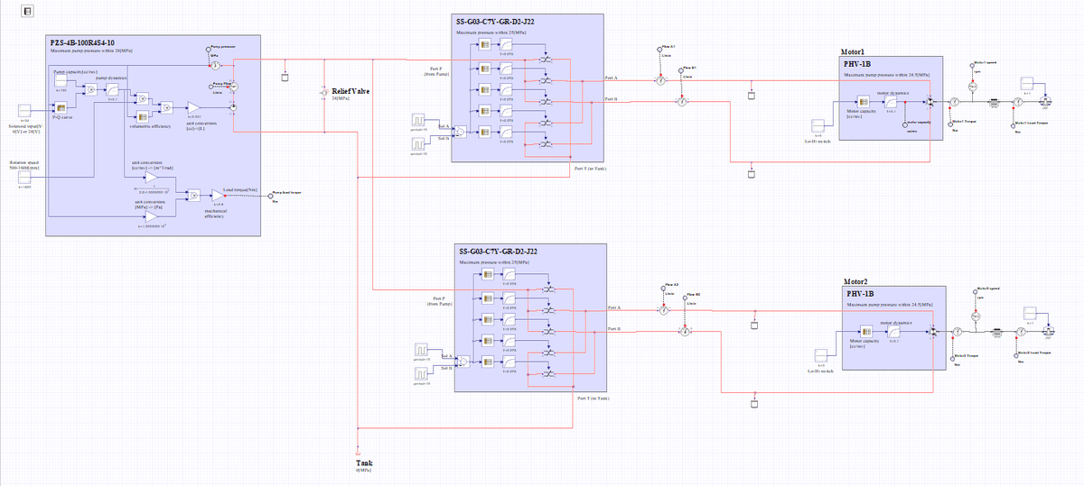
前回の記事では図1のポンプ・モータシステムをMapleSimでモデル化してみました(図2)。そして、Motor2の負荷を1.4倍にすると、当然ではありますが図3に示すように2つのモータの回転数に差が生じるようになります。今回はその差をなくすことを考えてみたいと思います。


回転数差の理由と対策を考えてみよう!
Motor2の負荷が高くなると、当たり前って言えば当たり前かもしれませんが、Motor2側に油が行きにくくなります。その分、Motor1側に油が多く行くようになって回転数差が生じます(図3上側)。
シンプルな対策はMotor2側の負荷が高くなってMotor2側の圧力が高くなっている分、Motor1側も同じ圧力になるようにMotor1側のバルブの出口にオリフィスを入れてやります。そうするとMotor1側とMotor2側の両方の圧力が均衡するので同じ流量になります。
MapleSimでモデル化
それではMapleSimでモデル化をしてみましょう。図4の緑色の部分が追加したオリフィス部分になります。緑色部分を拡大したものを図5に示します。
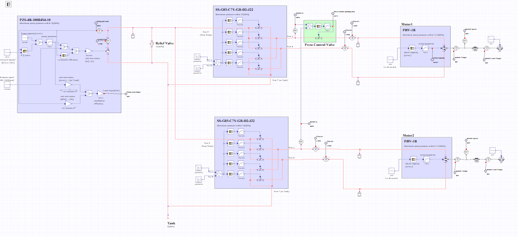
図5を見るとオリフィス以外に3つのブロックがありますね。
常に一定の負荷の差であれば固定の開口面積のオリフィスでもよいでしょう。しかし、負荷が変動することを考えて、他方(このモデルの場合はMotor2)の負荷による圧力と、自分側(このモデルの場合はMotor1)との圧力差によって開口を変化させることにしました。
まず、自分の側(Motor1)の圧力と相手の側(Motor2)の圧力との差分を計算します。自分の側が高ければ正の値になりますし、相手の側の圧力が高ければ負の値になります。つぎに「Looku Table 1D」の設定を図6に示していますが、他方に比べて自分の側の圧力が同じか高い場合にはメインバルブの開口面積よりやや大きめの0.4[cm^2]にしています。相手の方の圧力が高まるにつれて開口面積を小さくするようにしています。最後にこの作成した圧力制御弁(オリフィス)の応答として一次遅れブロックを使っています。時定数は0.1[s]を設定しました。


シミュレーションをしてみよう
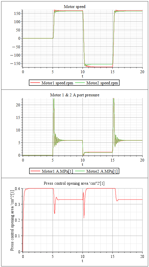
それでは作成したモデルのシミュレーションを実行してみましょう。結果は図7のようになります。Motor1のAポート側にだけ圧力制御弁を設置しているので、5秒から10秒と15秒から20秒の間の回転数差が図3の圧力制御弁を設置しなかったときに比べて低下していることがわかります。Motor1のBポートには圧力制御弁を設置していないため回転数差を生じていますね。なお、差が生じていますが図3に比べて差が少なくなっています。これはAポート側に設置した圧力制御弁が最大開口ではありますが背圧を高めているために差がやや減少しています。
今回は圧力制御弁の設置効果をわかりやすく見るためにMotor1のAポート側にだけ設置しましたが、Motor1とMotor2のどちらの負荷が高まるかもわかりませんし、モータの回転方向も正転逆転の2通りありますから、最終的にはMotor1とMotor2のそれぞれのAポートとBポートの4か所に設置しなければなりません。
【English】
Previously created Pump and Motor System
In the previous article, we modeled the pump-motor system shown in Figure 1 in MapleSim (Figure 2). In the previous article, we modeled the pump-motor system shown in Figure 1 in MapleSim (Figure 2). Then, if we increase the load on Motor2 by a factor of 1.4, there will naturally be a difference in the speed of the two motors, as shown in Figure 3. In this issue, we would like to consider reducing this difference.
Let's consider the reasons and countermeasures for the RPM difference!
When the load on Motor 2 is higher, it may be natural to say that oil does not go to the Motor 2 side as much as it should. This causes more oil to go to the Motor1 side, resulting in a difference in rpm (upper side of Figure 3).
A simple solution is to put an orifice at the outlet of the valve on the Motor 1 side so that the pressure is the same as on the Motor 2 side, where the pressure is higher. This will balance the pressure on both the Motor1 and Motor2 sides, resulting in the same flow rate.
Modeling with MapleSim
Now let's model it in MapleSim. The green area in Figure 4 is the added orifice. Figure 5 shows an enlarged view of the green area.
If you look at Figure 5, you see three blocks in addition to the orifice.
If the difference in load is always constant, an orifice with a fixed opening area would be acceptable. However, considering that the load fluctuates, we decided to change the orifice opening area according to the pressure difference between the pressure due to the load on the other side (Motor 2 in this model) and the pressure on our side (Motor 1 in this model).
First, the difference between the pressure of Motor1 and Motor2 is calculated; if the pressure on the Motor1 side is higher, it will be positive, and if the pressure on the Motor2 side is higher, it will be negative. If the pressure on the Motor 1 side is the same or higher than the other side, the opening area is set to 0.4 [cm^2], which is slightly larger than the opening area of the main valve. The opening area is reduced as the pressure increases toward Motor2. Finally, a first order delay block is used as the response of this created pressure control valve (orifice). A time constant of 0.1[s] was set.
Let's run a simulation
Now let's run a simulation of the created model. The results are shown in Figure 7. Since the pressure control valve is installed only on the A port side of Motor1, the RPM difference between 5 to 10 seconds and 15 to 20 seconds is lower than the result without the pressure control valve (Figure 3). You see that the B port of Motor 1 does not have a pressure control valve installed, resulting in a difference in RPM. Although a difference is observed, the difference is smaller than in Figure 3. This is because the pressure control valve installed on the A port side is at its maximum opening, but the back pressure is increased, so the difference is slightly reduced.
In this case, the pressure control valve was installed only on the A port side of Motor 1 to make it easier to see the effect of the installation. However, since we do not know which load may increase, Motor 1 or Motor 2, and there are two directions of motor rotation (forward or reverse), we must ultimately install the valve at four locations, the A and B ports of Motor 1 and Motor 2, respectively.
【Sample】
Created by MapleSim 2023
この記事が気に入ったらサポートをしてみませんか?