Mapleで制御工学の基礎虎の巻7「ECUで制御するなら離散時間システムでも検討しよう」
実際にシステムを制御する場合にはECU(Electronic Control Unit)によって実現することになります。これまではシステムを連続時間として考えてシステムの分析を行なってきましたが、ECUによって制御する場合にはシステムを離散時間として検討しなければなりません。今回の記事では離散時間としてシステムを検討する仕方と、離散時間として検討することによって連続時間では安定でも離散時間にすると不安定になってしまう例についても紹介したいと思います。
連続時間システムを離散化してみよう!
本記事ではMapleを使って連続時間システムを離散化して、システムの挙動を見てみることにします。まず本記事で使うシステム関連のライブラリとシステムの安定性を判定するための固有値計算のライブラリを読み込みます。
with(DynamicSystems);
with(LinearAlgebra);
本記事では次の伝達関数を離散化してみます。

Mapleでは次のコマンドで伝達関数をシステムとして定義できます。
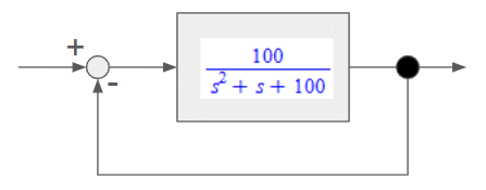
sys1 := TransferFunction(100/(s^2 + s + 100))本記事ではECUに制御を実装することによってシステムの挙動がどうなるかを見てみたいので、図1に示すようなフィードバックシステムを考えます。
今回は簡単に出力をフィードバックして目標値との差分をゲイン1として対象のシステムに入力するものとします。

フィードバックシステムにするMapleのコマンドは次のようになります。
フィードバックラインに伝達関数がないので第2引数は「1」としています。また、フィードバックをマイナスで結合するので第3引数の「connection」は「negativefeedback」としています。
sys2 := SystemConnect(sys1, 1, connection = negativefeedback);フィードバックしたシステムの伝達関数は次のようになります。

ここでフィードバックシステムの連続時間システムのままでのステップ応答を見てみましょう。Mapleのコマンドは次のようになります。
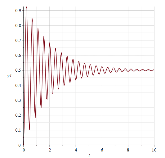
10[s]までの応答を見てみようと思うので第3引数の「duration」を「10」としています。図2に連続時間システムのステップ応答を示しています。振動はするものの収束していることがわかりますね。
ResponsePlot(sys2, Step(), duration = 10, gridlines)
それでは連続時間システムを離散化してみましょう。
まず、離散化するサンプリング時間を設定します。ここではサンプリング時間を0.01[s]としてみます。
SP := 0.01:Mapleでの伝達関数を離散化するコマンドは次のようになります。
ここでは前進差分で離散化するので「method」を「forward」とします。
sys2D := ToDiscrete(sys2, SP, method = forward):離散化した伝達関数を見てみましょう。
Mapleでのシステムを見るためのコマンドは以下になります。
PrintSystem(sys2D);離散化したシステムは以下のようになります。
離散時間システムなので「z」の関数になっています。

それでは、離散化したシステムのステップ応答を見てみましょう。
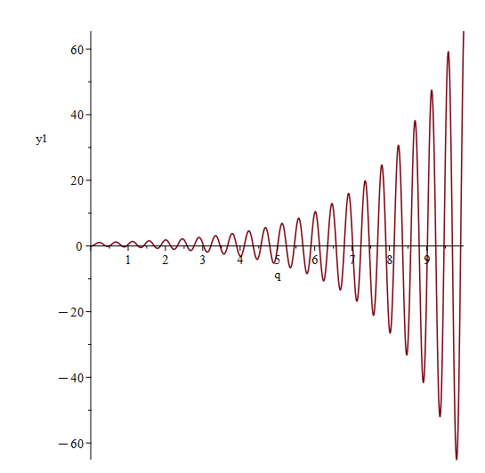
Mapleでの離散時間システムのステップ応答は以下のコマンドで見ることができます。図3にステップ応答を示します。
ResponsePlot(sys2D, Step(sampletime = SP, samplecount = floor(10/SP), discrete = true));あれ?
連続時間では収束していたのに、発散してますね。
連続時間システムでは安定なシステムも離散化することで不安定になってしまうこともあるのです。

離散時間システムの安定性を見てみよう!
それでは離散時間システムの安定性を調べてみましょう。
まず、離散時間システムの伝達関するを状態空間表現へ変換します。
Mapleのコマンドは以下となります。
sys2D_state := StateSpace(sys2D):状態空間表現のシステム行列の固有値で安定性を判断するため、状態空間モデルにしたモデルからシステム行列部分を抜き出します。Mapleのコマンドは以下となります。
A := sys2D_state:-a
抜き出したシステム行列の固有値を計算します。
Eigenvalues(A);
計算したすべての固有値の絶対値が1より小さければ漸近安定となります。なお「1」となる場合は限界安定となり、収束するにはいくつかの条件が必要になります。これ以上、詳しく知りたい人は専門書で勉強してね。
abs(Eigenvalues(A));先ほどのシステムの固有値の絶対値を計算すると、2つとも1より大きくなっていますね。そのため不安定であり、ステップ応答も発散してしまったのですね。

サンプリング時間を短くしてみよう!
連続時間システムで安定なのに離散時間システムにすると不安定になってしまう原因の1つにサンプリング時間があります。サンプリング時間が大きいと不安定になる場合があるのです。そこで今回はサンプリング時間を0.001[s]にしてシステムの応答を見てみましょう。
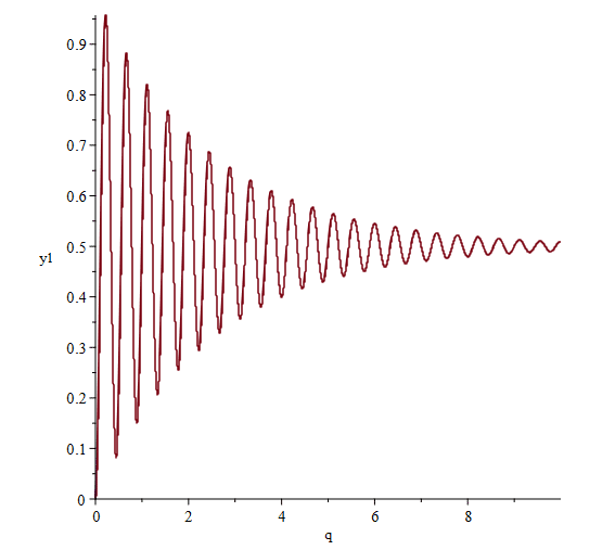
図4にサンプリング時間を0.001[s]にしたときのステップ応答を示しています。収束していることがわかります。
なお、固有値の絶対値もすべて「1」より小さくなっていますね。
対象システムをECUによって制御する場合には、サンプリング時間によってシステムが不安定になってしまう場合もあります。対象のシステム、設計した制御システムによって安定化に必要なサンプリング時間を安定解析をした上で設定するしようにしましょう。


補足
今回はシステムをECUによって制御する場合の、離散時間としての課題を見てきましたが、ECUを利用する場合には離散時間の課題だけでなく、ECUの入出力の分解能の課題もあります。 ECUの入出力の分解能が粗いと離散時間のステップが粗い場合と同じように安定しなくなる場合もあります。ECUを用いてシステムを制御する場合には、ECUの計算ステップや入出力の分解能をしっかりと検討しましょう。
【English】
The actual control of the system is realised by means of ECUs. In the previous articles, the system has been analysed as a continuous-time system, but when the system is controlled by an ECU(Electronic Control Unit), the system must be analysed as a discrete-time system. In this article, I would like to introduce how to analyse the system as a discrete-time system, and also examples where the system is stable in continuous time but becomes unstable in discrete time by analyzing the system as a discrete-time system.
Let's discretize a continuous-time system!
In this article, we will discretise a continuous-time system using Maple to see how the system behaves. We will first load the system-related libraries used in this article and the eigenvalue calculation library to determine the stability of the system.
with(DynamicSystems);
with(LinearAlgebra);
In this article, the following transfer functions are discretised.

In Maple, transfer functions can be defined as a system with the following command.
sys1 := TransferFunction(100/(s^2 + s + 100))In this article, we want to see how the system behaves by implementing control in the ECU, so we consider a feedback system as shown in Figure 1. For simplicity, we assume that the output is fed back and the difference from the target value is input to the target system. Note that the gain to the difference is set to ‘1’ for simplicity.

The Maple command to make the feedback system is as follows. The second argument is set to ‘1’ because there is no transfer function in the feedback line. Also, the third argument ‘connection’ is set to ‘negativefeedback’ because the feedback is combined with a negative value.
sys2 := SystemConnect(sys1, 1, connection = negativefeedback);The transfer function of the fed back system is as follows.

Now let's look at the step response of the feedback system as it is in a continuous time system, the Maple command looks like this: we are going to look at the response up to 10[s], so we set the third argument ‘duration’ to ‘10’. The step response of a continuous-time system is shown in Figure 2. You can see that the system is oscillating but converging.
ResponsePlot(sys2, Step(), duration = 10, gridlines)
Now let's discretise the continuous-time system. First, set the sampling time to be discretised. Let's set the sampling time to 0.01 [s].
SP := 0.01:The command to discretise the transfer function in Maple is as follows. Here, ‘method’ is set to ‘forward’ as the discretisation is done by forward differences.
sys2D := ToDiscrete(sys2, SP, method = forward):Let's look at the discretised transfer function - here are the commands to look at the system in Maple.
PrintSystem(sys2D);The discretised system looks like this. As it is a discrete-time system, it is a function of ‘z’.

Now let's look at the step response of a discretised system: the step response of a discrete-time system in Maple can be seen with the following command. The step response is shown in Figure 3.
ResponsePlot(sys2D, Step(sampletime = SP, samplecount = floor(10/SP), discrete = true));Huh? The response was converging in continuous time, but it's diverging. A system that is stable in a continuous-time system can become unstable when it is discretised.

Let's check the stability of a discrete-time system!
Now let's check the stability of the discrete-time system. First, we will convert the transfer of a discrete-time system into a state-space representation, the Maple commands are as follows
sys2D_state := StateSpace(sys2D):To determine stability by the eigenvalues of the system matrix in the state-space model, the system matrix part is extracted from the model made into a state-space model. The Maple commands are as follows.
A := sys2D_state:-a
Calculate the eigenvalues of the extracted system matrix.
Eigenvalues(A);
If the absolute value of all calculated eigenvalues is less than 1, the system is asymptotically stable. Note that if the value is ‘1’, the system is marginal stable, and several conditions are required for convergence. If you want to know more about this, read and learn from books.
abs(Eigenvalues(A));If you calculate the absolute values of the eigenvalues of the system you have just described, you find that they are both greater than 1. That is why it is unstable and the step response has diverged.

Let's shorten the sampling time!
One of the causes of instability in a discrete-time system when the system is stable in a continuous-time system is the sampling time. If the sampling time is large, the system may become unstable. So let's look at the response of the system with a sampling time of 0.001[s]. Figure 4 shows the step response when the sampling time is set to 0.001 [s]. It can be seen that the system is converging. In addition, the absolute values of the eigenvalues are all smaller than ‘1’. When the target system is controlled by an ECU, the sampling time may cause system instability. Set the sampling time required for stabilisation according to the target system and the control system you have designed, after conducting a stability analysis.


Additional explanation
In this article, we have looked at the issues as discrete time when the system is controlled by ECUs, but when using ECUs, there are not only discrete time issues, but also issues with the resolution of the ECU inputs and outputs. If the resolution of the inputs and outputs of an ECU is coarse, the system may not be as stable as if the discrete-time steps were coarse; when using an ECU to control a system, the calculation steps and the resolution of the inputs and outputs of the ECU should be carefully considered.
【Sample】
Created by Maple 2024.1
