
MapleSimで超簡単な油圧モデルを作ってみた#2(可変開口オリフィスへの変更とリリーフバルブの追加)

前回作成した固定容量ポンプと固定オリフィスだけの超簡単な油圧モデルを今回は改造してみます。はじめに固定オリフィスと可変オリフィスに変えて油圧回路の動きを見てみます。そして、その後にリリーフバルブを追加します。
可変オリフィスへの変更
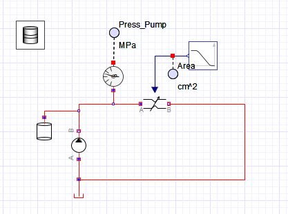
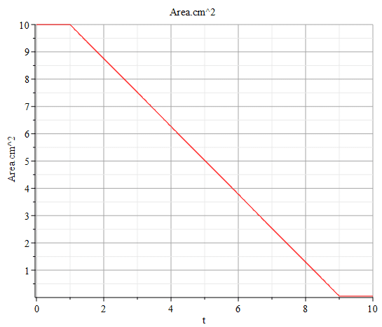
前回作成した油圧回路をベースに図1に示すように固定オリフィスブロックを可変オリフィスブロックに変更します。可変オリフィスに変更したので、外部から開口面積を入力するようになります。開口面積を指定する数値入力ブロックもも追加して可変オリフィスに接続します。可変オリフィスの開口面積は最初の開口面積は10[cm^2]として、1秒後から開口面積を徐々に小さくして8秒後(時系列で言うと9秒の時)に0.1[cm^2]まで小さくします(図2)。
この状態でシミュレーションを実行(実行ボタン「▶️」を押す)しても動きはしますが、かなりモッサリした動きなっているので、設定を考えなければなりません。
1つ目は、チャンバー容量を小さくしようと思います。前回は動けばいいくらいの設定だったので、0.1[m^3]にしていましたが、これは大きすぎるので、チャンバーの容積を0.001[m^3]に変更します。チャンバー容積が大きいと流量の変化に対して圧力の変化がゆっくりとなってしまうためです。もちろん配管やホースが太く長い場合には容量は大きいので、大きく設定してもよいです。しかし、この容量は油圧シミュレーションの経験者から言わせてもらうと、かなりの曲者と言えます。これだけでノウハウ集を作れるくらいの曲者具合なのですが、簡単に言えば、流量の変化に応じて適宜調整して実際の油圧変化に近いものにしないとならないということです。経験がないとどう設定してよいかかなり悩むところです。ゆえに曲者だと言うことなのです。作動油は体積弾性率が非常に大きいため、ほとんど圧縮性のない流体(非圧縮性流体)として考えてよいです。しかし、計算の都合上、ピンっと圧が立って大きな力を生じさせてしまうとシミュレーションが発散してしまうので、程よい調整を必要とします。
2つ目の変更は、先に述べた体積弾性率(圧縮性などとも言う)の値です。ドラム缶マークのブロックに設定があり、デフォルトでは8000[bar]となっています。作動油の体積弾性率は空気の混入量や温度によって変わってきますが、おおよそ14000〜19000[bar]程度なので、デフォルト設定はかなり小さい値となっていると言えます。そのために作動油の流量変化に対してかなりモッサリとした油圧の変化となってしまっています。
それじゃぁ、ザクっと14000[bar]にしてみると、残念ながらエラーになってしまいます。計算が発散してしまっているようです。ちょこっとソルバの設定も変えてみましたが、どうにもエラーを回避できないので、体積弾性率の変更は諦めることにしました。なお、10000[bar]くらいまでならば今回のシンプルな回路では、なんとか耐えられますが、それを超えてくると不安定になるので、とりあえず当面はデフォルトの値のままとしておくことにします。
>今度専門家に聞いてみようと思います。打開策がされば記事を更新してお知らせします。
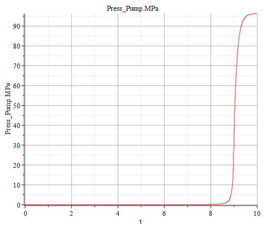
さて、こうして変更した可変オリフィスのシミュレーション結果は図3のようになります。0.1[cm^2]まで開口を閉じると95[MPa]を超えてくることが見て取れます。こんな圧力だと一般的な産業機械で使われている油圧機器では壊れてしまいますから、次に回路を保護するためにリリーフバルブを設置したいと思います。
リリーフバルブの追加
図1の油圧回路のモデルに、図4のようにポンプの左側にリリーフバルブを追加します。リリーフバルブの設定は図5に示します。38[MPa]でクラックし開口が開き始めて、40[MPa]でフルオープンになるように設定しています。クラックするまでは完全にクローズさせようと思いAcloseの値をゼロにするとエラーになってしまったので、小さい値にして回避しています。
>これについても今度専門家に聞いてみようと思います。打開策がされば記事を更新してお知らせします。
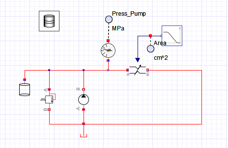
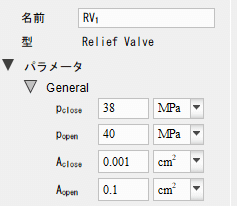
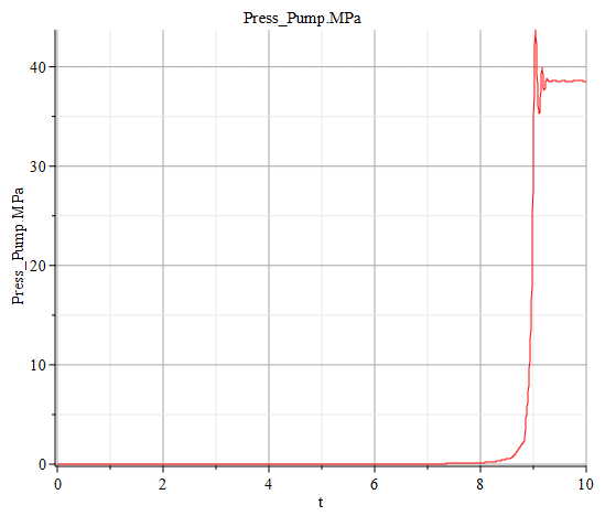
図6にリリーフバルブを追加した時のシミュレーション結果を示します。ピーク圧は40[MPa]を超えていますが、リリーフバルブが開くことでポンプ圧が40[MPa]を超えないようになりました。
実際には作動油が低温で硬い時にはもっとピークが立ちますし、リリーフバルブの応答性が悪くても圧力の上昇に応答しきれなくてピーク圧が立つ傾向になります。また、ポンプ流量に対して十分なリリーフ開口がなければ圧力を回路保護圧まで減圧することができません。現状のリリーフバルブはかなり理想的な動きをしている前提のモデルですので、上記のことを頭に入れてシミュレーションするか、検討できるモデルに改造するとよいでしょう。ただし、あまりモデルに凝りすぎて芸術作品を作るようなことを避けるべきと思います。趣味ならいくらでも極めてよいですが、仕事での開発となると設計に使える時間とのトレードオフや、今後の開発での流用性なども考えて、特定の人だけの代物にならないようにしなければ無駄なものになってしまいます。
ちょっとだけリリーフバルブ選定の注意
リリーフバルブを通過する流量を確認しましょう!
通過させてよい最大流量というものがあります。大抵はスペック表には「瞬間」と「定常」と2つ書かれていることが多いです。「瞬間」とは瞬間的に、まぁ100[ms]とか200[ms]とか定められた時間に通過してよい瞬間最大流量です。そして「定常」とは、あまり定常的にリリーフバルブに流し続けるのはいかがなもんかと思いますが、定常的に延々と流しても壊れない流量です。「瞬間」も「定常」でも最大流量を守らないと、油圧回路の安全を守るべきリリーフバルブ自体が壊れてしまいますので注意しましょう。
これ以外にも守らなければならないスペックがたくさんありますので、興味があれば油圧機器メーカーのスペック表を見てみるとおもしろいかもしれません。
【English】
Change to Variable Orifice
Based on the hydraulic circuit created previously, change the fixed orifice block to a variable orifice block as shown in Figure 1. Now that the orifice has been changed to a variable orifice, the opening area is input from the outside. A numerical input block to specify the opening area is also added and connected to the variable orifice. The initial opening area of the variable orifice is 10[cm^2], and the opening area is gradually reduced from 1 second to 0.1[cm^2] after 8 seconds (at 9 seconds in the time series) (Figure 2).
If I run the simulation in this state (press the Run button "▶️"), it will move, but the result of the simulation will be quite different from reality, with a slower movement, so I need to rethink the settings.
First, I would like to reduce the chamber capacity. The previous setting was 0.1[m^3] because it was set just enough to move, but this is too large, so we will change the chamber volume to 0.001[m^3]. This is because a large chamber volume causes the pressure to change slowly in response to changes in flow rate. Of course, if the piping and hoses are large and long, the volume can be set larger. However, this capacity is a very difficult problem to solve, if I may say so from an expert in hydraulic simulation. The level of difficulty is such that a collection of know-how could be made on this alone. Simply put, it must be adjusted accordingly according to changes in flow rate to be close to actual changes in hydraulic pressure. Without experience, it is quite difficult to know how to set this up. Hence, this is a difficult problem. Since hydraulic fluid has a very large volume modulus of elasticity, it can be thought of as an almost incompressible fluid. However, for the convenience of the calculation, if the pressure suddenly stands up and generates a large force, the simulation will diverge, so a moderate adjustment is required.
The second change is the volumetric modulus (also called compressibility) value mentioned earlier. The setting is located in the block marked with the drum symbol and defaults to 8000[bar]. The volumetric modulus of elasticity of hydraulic fluid varies depending on the amount of air and temperature, but it is approximately 14,000 to 19,000 [bar], so the default setting is a fairly small value. Therefore, the hydraulic oil pressure changes are quite slow in response to changes in the hydraulic oil flow rate.
So I tried setting the value of the volumetric modulus to 14000 [bar], but unfortunately I get an error. The calculations seem to have diverged. I tried changing the solver settings a little bit, but I could not avoid the error, so I decided to give up on changing the volumetric modulus. The simple circuit can withstand up to about 10000[bar], but it becomes unstable when it exceeds that level, so for the time being, I will leave the default values as they are.
>I will ask the experts next time. If a breakthrough is found, I will update this article and let you know.
Now, the simulation result of the variable orifice thus modified is shown in Figure 3, where it can be seen that the pressure exceeds 95[MPa] when the orifice is closed to 0.1[cm^2]. At this kind of pressure, the hydraulic equipment used in general industrial machinery would break down, so next I would install a relief valve to protect the circuit.
Addition of Relief Valve
Add a relief valve to the left side of the pump as shown in Figure 4 to the model of the hydraulic circuit in Figure 1. The settings of the relief valve are shown in Figure 5, where it is set to crack and open at 38[MPa] and fully open at 40[MPa]. In fact, we want the valve to be fully closed until it cracks, but setting the value of "Aclose" to zero would have resulted in an error, so I set it to a smaller value to avoid the error.
>I will ask an expert about this as well next time. If a breakthrough is found, I will update this article and let you know.
Figure 6 shows the simulation results when a relief valve is added. The peak pressure exceeds 40[MPa], but the relief valve opens so that the pump pressure does not exceed 40[MPa].
In actuality, the peak pressure tends to rise more when the hydraulic oil is cold and hard, or when the relief valve is not responsive enough to respond to the pressure increase. Also, if there is not enough relief opening for the pump flow rate, the pressure cannot be reduced to the circuit protection pressure. The model assumes that the current relief valve operates in a fairly ideal manner, so it is advisable to simulate it with the above in mind or modify the model to allow for consideration. However, I think you should avoid making a work of art by being too obsessed with modeling. If it is a hobby, no one will complain if you continue to make as elaborate a model as you like, but if it is development for work, you must consider the trade-off with the time available for design and the appropriateness for future development, and avoid making a model that is unique to a particular person.
A little note on relief valve selection
Check the flow rate through the relief valve!
There is a maximum flow rate that is allowed to pass through the system. Most of the time, there are two specifications written on the spec sheet: "instantaneous" and "steady".The "instantaneous" maximum flow rate is the flow rate that is allowed to pass within a certain period of time, for example, 100[ms] or 200[ms].And "steady" is the flow rate that will not break even if the flow is steady and uninterrupted. Of course, it is not a good idea to keep the relief valve flowing constantly. Note that if the maximum flow rate is not maintained, whether "instantaneous" or "steady," the relief valve itself, which is supposed to protect the safety of the hydraulic circuit, will break.
There are many other specifications that must be followed, so if you are interested, it may be worthwhile to look at the hydraulic equipment manufacturer's specifications list.
【Sample Model】
Created by MapleSim 2023