
MapleSimで超簡単な油圧モデルを作ってみた

MapleSimを使ってどこまで油圧モデルを作れるかチャレンジしてみようと思い、まずは「Hello World」的な超簡単な油圧モデルを作ってみました。
タンクからポンプで作動油を汲み上げて回路へと送り出し、オリフィスを介してタンクへ戻すとても簡単な油圧回路です。作った油圧回路を図1に示します。
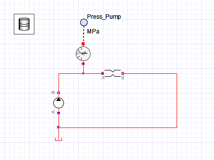
MapleSimの油圧ライブラリからポンプ、オリフィス、タンクをポチッと配置して、結線するだけで簡単に作れます。回路から浮いているところにあるドラム缶?っぽいアイコンは作動油の特性を設定するブロックです。油圧のシミュレーションをするときは必ず1つ置かないといけません。デフォルトで値が入っているので、初心者は設定を変えずにそのままでも、それなりの計算結果になります。
ポンプ圧を測りたいのでプローブを設置します。測りたいところ(回路の線上)で右クリックしてプローブを選ぶだけで設置できます。今回はMPaで結果を表示したかったので、圧力センサをプローブと油圧回路の間に設置しています。これを設置しないとPa表示になるので、桁数が大きくなってパッと読みにくいです。
あとはポンプの流量を100[L/min]、オリフィスの開口面積を10[cm^2]に設定して実行ボタン「▶️」を押すだけです。
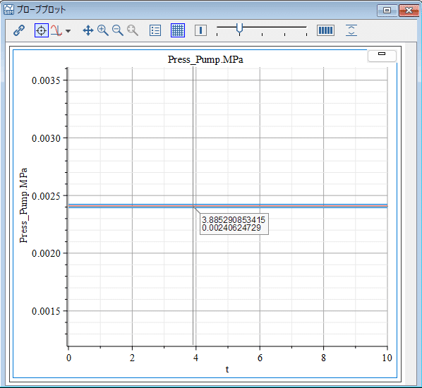
計算結果を図2に示します。
ポンプ圧は0.0024[MPa]になっていますね。オリフィスにポンプから一定流量が流れ込んでいるので、圧力も一定になっています。
回路にチャンバーを入れてみる
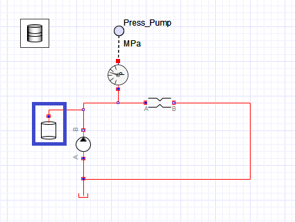
図1の油圧回路に図3に示すように「チャンバー」を入れてみましょう。
油圧ライブラリからポチっと置いて、回路上にくっつけるだけです。
チャンバーって何?
簡単に言えば、回路上の容積です。
今回のモデルでは0.1[m^3]に設定しました。
チャンバー(容積)を追加することで、そこに流れる作動油の量と出ていく作動油の量から圧力が計算されるようになります。
ポンプから吐き出される作動油が流入する作動油の量です。
どこにも出ていかなければ圧力はガンガン上がります。
しかし、オリフィスがありますよね。
オリフィスの下流はタンク(0[MPa])なので、上流であるポンプ側の圧力が上昇すると、オリフィスを通過する流量が増えます。要するにチャンバーから作動油が流出していきますね。
こうしてポンプからの流入する作動油と、オリフィスから流出する作動油の流量が釣り合ったところで圧力が安定するのです。
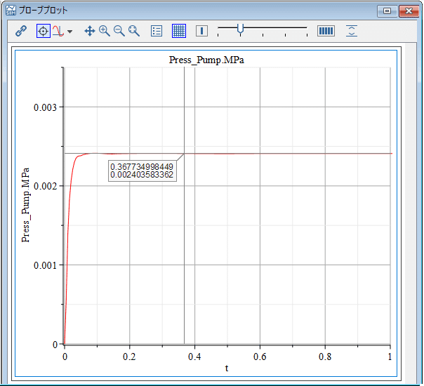
その様子がわかるのが、図3の油圧モデルの実行結果である図4です。
100[ms]くらいで、先ほど実行した図1の油圧モデルの実行結果のポンプ圧とだいたい同じになっていますね。
チャンバーを設置することで、油圧のダイナミックな挙動を見ることができるようになるのです。
気をつけないといけないこと
チャンバーを追加した方が、油圧回路っぽい結果になるので、入れたくなりますが、よく考えて入れないと油圧振動を起こしてしまったり、チャンバーの個数が増えてくると、やたらと計算に時間がかかってきます。
なのでチャンバーを無闇に設置しないようにしてみましょう!
とは言え、どこに設置したらええねん!?
となるでしょう。
残念ながら、こればっかりは経験がものをいうので、簡単な油圧回路をいろいろと組んで経験を積むしかありません。
ソルバも大事
油圧モデルのシミュレーションは波形がかなり振動します。
いわゆるスティッフなシステムになる場合が多いからでしょうね。
なので、油圧システムを計算するときのソルバはスティッフなシステム対応のものを選ぶとよいでしょう。
今回もソルバは「Rosenbrock(stiff)」を選んでいます。
【English】
I tried to make a very simple hydraulic model in MapleSim.
I decided to challenge myself to see how far I could go with MapleSim to create a hydraulic model, then I started with a very simple "Hello World" type of hydraulic model.
Figure 1 is a very simple hydraulic circuit in which hydraulic oil is pumped from the tank to the circuit and returned to the tank via an orifice.
It's easy to make, just pop in a pump, orifice, and tank from MapleSim's hydraulic library and wire it up. The icon that looks like a drum floating out of the circuit is a block that sets the hydraulic oil properties. It must be placed when simulating hydraulic pressure. The values are included by default, so beginners can leave the settings as they are and still get reasonable calculation results.
I want to measure the pump pressure, so I install a probe. Simply right-click where you want to measure (on the line of the circuit) and select the probe. In this case, I wanted to display the results in MPa, so I installed a pressure sensor between the probe and the hydraulic circuit. If you do not install this, it will display in Pa, which has a large number of digits and is difficult to read quickly.
All that remains is to set the pump flow rate to 100[L/min] and the orifice opening area to 10[cm^2] and press the Run button "▶️".
The calculation results are shown in Figure 2. You see that the pump pressure is 0.0024 [MPa]. Since a constant flow is flowing from the pump into the orifice, the pressure is also constant.
Let's put a chamber in the circuit.
Let's put a "chamber" in the hydraulic circuit shown in Figure 1, as shown in Figure 3. Just pop it in from the hydraulic library and stick it on the circuit.
What is a chamber?
Simply put, it is the volume on the circuit. In this model, we set it to 0.1 [m^3]. Adding a chamber (volume) allows the pressure to be calculated from the amount of hydraulic fluid flowing into it and the amount of hydraulic fluid going out. The amount of hydraulic oil that flows in is the amount of hydraulic oil that is discharged from the pump. If it doesn't go out anywhere, the pressure will go up a gazillion times. But there is an orifice in this circuit, right? Downstream of the orifice is the tank (0[MPa]), so as the pressure on the pump side, which is upstream, increases, the flow rate through the orifice increases. In essence, the hydraulic oil flows out of the chamber, right? Thus, the pressure stabilizes when the flow rate of hydraulic oil flowing in from the pump and the flow rate of hydraulic oil flowing out of the orifice are balanced. You can see this in Figure 4, the result of the hydraulic model run in Figure 3, which is about 100[ms], which is roughly the same as the pump pressure in the hydraulic model run in Figure 1 that we just ran. By placing the chamber, we can see the dynamic behavior of the hydraulic pressure.
Be careful!
It is tempting to add chambers because the result will be more like a hydraulic circuit, but if you don't think carefully, you may cause hydraulic oscillations, and as the number of chambers increases, it will take a lot of time to calculate. So, let's try not to install the chambers without any thought! However, where should we place them? You may ask yourself, "Where should I place the chambers? Unfortunately, experience is the key to success in this matter, so the only way is to gain experience by setting up various simple hydraulic circuits.
The choice of solvers is also important.
The simulation of the hydraulic model has quite oscillating waveforms. This is probably because they are often so-called stiff systems. Therefore, it is recommended to choose a solver that supports stiff systems when calculating hydraulic systems. In this case, too, "Rosenbrock(stiff)" was selected as the solver.
この記事が気に入ったらサポートをしてみませんか?