
MapleSimでLookup Table 2Dの使い方

モデル化でよく使う補間計算のうち、今回は2次元補間について紹介します。一次元補間の使い方については、以前の記事「MapleSimでLookup Table 1Dの使い方」を参照してください。
一次元補間の説明ではcsvファイルを読み込む方法と直接MapleSimに設定する方法「inline」の2つの方法について記載しましたが、基本的な方法は一次元補間も二次元補間も同じなので、ここでは「inline」による方法を説明します。
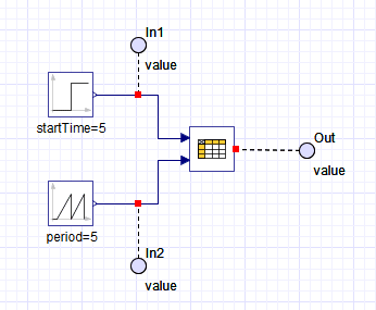
まず図1のように「Lookup Table 2D」ブロックとそれへの2つの入力として、第1入力用に「Step」ブロック、第2入力用に「Saw Tooth」ブロックを置いて接続します。2つの入力と出力を見るために「probe」を付けます。
「Lookup Table 2D」ブロックの設定
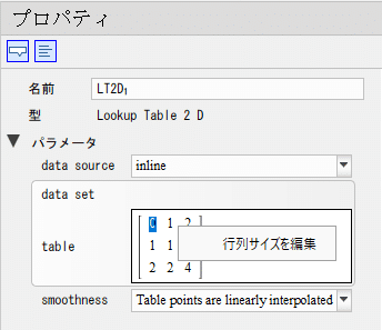
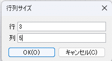
「Lookup Table 2D」ブロックのテーブルサイズの変更方法は、図2のように、「table」の行列の上あたりにマウスカーソルを持っていき、右クリックをすると「行列サイズを編集」と出てくるのでクリックします。クリックすると図3のように行列の設定ダイアログボックスが出てきます。今回は3行5列と設定しておきます。「OK」ボタンを押すと図4のように3行5列になります。

次に図5のように「table」の数値を設定します。
1列目(縦方向)は「0 1 2」となっていますが、最初の「0」は意味がなく、2つ目以降の「1」と「2」が意味のある数値になります。「Lookup Table 2D」ブロックの第1入力(今回でいうと「Step」ブロック)に対応するものです。
今度は1行目(横方向)を見てみましょう。「0 1 5 8 9」となっています。こちらも最初の「0」は意味がなく、2つ目以降の「1 」「5 」「8」「 9」が意味のある数値になります。こちらは「Lookup Table 2D」ブロックの第2入力(今回でいうと「Saw Tooth」ブロック)に対応するものです。
残りの2行2列から3行5列の数値が、1行目と1列目の数値に対応する出力の値になります。例えば、第1入力(1列目)が「2」で第2入力(1行目)が「8」だとすると出力は「6」となります。
「Lookup Table 2D」の設定にもよりますが、間の数値は線形補間された値になります。また、外挿計算は内挿計算の最後の2つの値の延長として計算されます。

入力ブロックの設定
次に「Lookup Table 2D」を使ってみるために、入力ブロックを設定します。「Lookup Table 2D」の第1入力の「Step」ブロックの設定は図6のようにします。5秒まで1を入力し、5秒以降は2にステップ状に変化します。
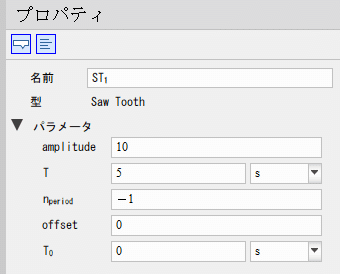
「Lookup Table 2D」の第2入力の「Saw Tooth」ブロックの設定は図7のようにします。0秒(出力値0)から5秒(出力値10)まで直線的に変化します。この変化を5秒周期で繰り返します。

実行結果
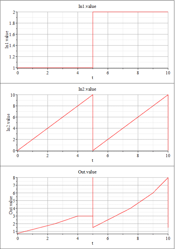
実行結果を図8に示します。
結果の1行目は第1入力、2行目は第2入力、3行目が「Lookup Table 2D」の出力です。
出力の4秒から5秒は数値が変化していませんね。図5の設定値を見ると、第1入力が1のときには第2入力が8以降は同じ数値になっています。このように最後の2つを同じ数値にすることで外挿計算時に頭打ちもしくは底打ちにすることができます。第2入力を頭打ちになるように設定していない第1入力が2にした9秒以降の出力を見ると第2入力の最後の2つの値によって延長された計算結果になっていますね。
あと出力で気になるところは5秒のところのピークだと思います。
これはMapleSimの仕様だと思うのですが、第1入力側と第2入力の切り替えは、順番に行われるため、最初に第1入力が2に切り替わった段階での出力結果に瞬時的になったあと、第2入力も切り替わり0になるのだと思います。そのために5秒のときの出力が10秒のときの出力と同じ値に瞬時的になってしまったのでしょう。
こういった仕様を理解して使わないと、モデルが複雑になっていくに従って「あれ?おかしいぞ」と困ることになるかもしれませんので、気を付けましょう!
【English】
Among the interpolation calculations commonly used in modeling, this article introduces 2D interpolation. For more information on how to use one-dimensional interpolation, please refer to the previous article "Using Lookup Table 1D in MapleSim".
In the explanation of one-dimensional interpolation, we described two methods: one is to read a csv file and the other is to set it directly in MapleSim "inline." Since the basic method is the same for both one-dimensional and two-dimensional interpolation, we will explain the "inline" approach here.
First, connect the "Lookup Table 2D" block and the two inputs to it as shown in Figure 1, placing a "Step" block for the first input and a "Saw Tooth" block for the second input.
Configure the "Lookup Table 2D" block
To change the table size in the "Lookup Table 2D" block, place the mouse cursor over the "table" matrix as shown in Figure 2, right-click, and click "Edit Matrix Size". Clicking on it will bring up the matrix settings dialog box as shown in Figure 3. In this case, we set 3 rows and 5 columns. Click the "OK" button to set 3 rows and 5 columns as shown in Figure 4.
Next, set the "table" values as shown in Figure 5.
The first column (vertical) is "0 1 2," but the first "0" is meaningless, and the second and subsequent "1" and "2" are meaningful values. This corresponds to the first input of the "Lookup Table 2D" block (in this case, the "Step" block).
Next, let's look at the first row (horizontally). The first "0" in the first line is not a "0" but a "0". The first "0" is meaningless, and the second and subsequent "1," "5," "8," and "9" are meaningful numbers. This one corresponds to the second input of the "Lookup Table 2D" block (in this case, the "Saw Tooth" block).
The values in the remaining part (row 2, column 2 to row 3, column 5) are the output values corresponding to the values in the first row and column 1. For example, if the first input (row 1) is "2" and the second input (row 1) is "8," the output will be "6.
Depending on the settings of "Lookup Table 2D," the values in between will be linearly interpolated. Also, the extrapolation is calculated as an extension of the last two values of the interpolation.
Input block settings
Next, to try using "Lookup Table 2D," set up the input blocks. The "Step" block for the first input of "Lookup Table 2D" should be set as shown in Figure 6, with "1" output for up to 5 seconds, and "2" output after 5 seconds. The "Saw Tooth" block setting for the second input of Lookup Table 2D is shown in Figure 7, and changes linearly from 0 seconds (output value 0) to 5 seconds (output value 10). This change is repeated in a 5-second cycle.
Execution Result
The execution results are shown in Figure 8. The first line of the result is the first input, the second line is the second input, and the third line is the output of "Lookup Table 2D".
We see that the values do not change from 4 to 5 seconds in the output. Looking at the set values in Figure 5, when the first input is 1, the second input is the same value after 8. Thus, by setting the last two to the same numerical value, you can set upper and lower limits when extrapolating. If you look at the output after 9 seconds when the first input is set to 2 and the second input is not set to the upper limit, the calculation result is extended by the last two values of the second input.
The other thing I'm wondering about with the output is the peak at 5 seconds. I think this is a MapleSim specification. I think this is because the switching between the first and second input sides did not take place at the same time, and as a result of the change in the first input and the change in the second input in turn, the calculation results were displayed, especially when only the first input changed and the value of the second input did not change.
If you do not understand and use this kind of specification, you may be in trouble as the model becomes more complex.
【Sample】
Created by MapleSim 2023
この記事が気に入ったらサポートをしてみませんか?