[Flight Recorder for RC] Part 2/Off-Board Type

[Part 1: I made it. ] is here. ( sorry only Japanese )
A while ago, I introduced the outline. In this article, I will explain the off-board type flight recorder for RC.

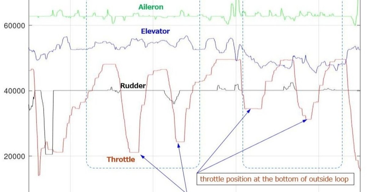
The above graph is a log when I performed the maneuvers called "Sportsman" in Japan. I did it with a trainer RC plane Serena Lt .
The green graph shows the movement of the aileron stick. Blue shows the elevator. Black shows the rudder. And red is throttle.
Schedule of SPORTSMAN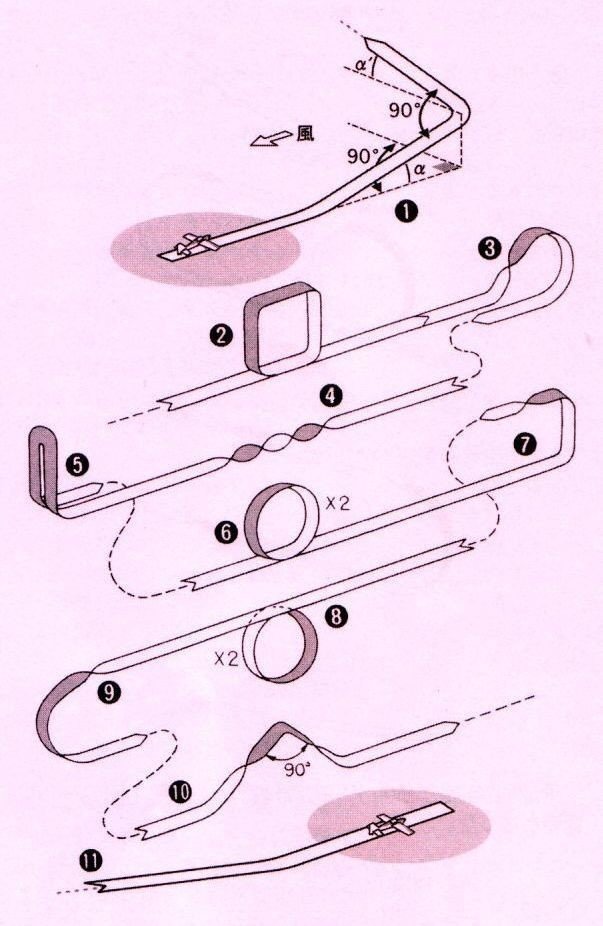
「日本無線航空会規則 平成27年度 スポーツマン級のパターン」より引用
1. Take Off
2. Square Loop
3. Half Reverse Cuban 8
4. Two Rolls
5. Stall Turn
6. Two Inside Loops
7. Half Square Loop with 1/2 Roll
8. 2 Outside Loops
9. Split S
10. Cobra Roll with 1/2 Rolls
11. Landing
How was I operating the elevator during two loops?
I expanded the graph. From the stall turn -> two inside loops -> half square loop with 1/2 roll -> two outside loops.
I think that I only operate the elevator in a circular shape while looking at the aircraft's movement.

・SerenaLt is a semi-symmetrical airfoils trainer, so the angle on the down side is increased by the function of my propo.
・It was a little cross wind. when I'm performing the loop, I operate the rudder as the plane go there and come here.
・Near the bottom of the loop, throttle opening angle is different for inside loop and out side loop. Is it psychological? Or for the semi-symmetrical shaped wing?
・I was manipulating the rudder in the opposite direction in the actions of inside loop and outside loop.
・The wind was blowing for the small trainer airplane, so the airplane was shaking. I was controlling the aileron even during level flight.
・I am operating the aileron near the bottom for inside loop and outside loop.
・Small plane, so I wanted to check the attitude of the plane when it was in the position seen from the side, and I swung the wing.
Hanno Prettner's maneuvering technique analyzed from flight recorder
Article of radio control technical magazine of April, 1975 issue
Click the image to enlarge. But, this is a Japanese article.


In the first half of the 1970s, a Japanese magazine company that was publishing the radio control technology magazine made a flight recorder of the method of monitoring the transmitted radio waves of the flyer, brought it to the competition, and analyzed the flyer's control technique.
The article described the necessity of a flight recorder for radio controlled aircraft. But for some reason it disappeared without being popular.
Modern version flight recorder for RC
It seems that various methods were invented in the early days of radio control for proportional, and the method of transmitting the target angle to the RC servo by the pulse width has become the mainstream. Currently, serial bus system that directly receives digital data is also used.
Nowadays, it is difficult to monitor the signals of other radio transmitters. However, if you place one of the paired receivers on the ground, then you can record the signal from the receiver. Therefore, I think it is possible to make a flight recorder similar to of 1970s, and if we use a serial bus, we can easily import it to a PC.
That's why I decided to make it. First, check the bus specifications.
XBUS/JR SPECIFICATONS
An overview of the XBUS specifications is publicly available and can be downloaded from the web site RC DEPOT HELI.
・ 3.3V Half Duplex Transmission
・ 8bit, 1 start bit, 1 stop bit, non parity, LSB first
・ Idle Hi Level
・ 250kbps BER under 1%
S-BUS/FUTABA SPECIFICATONS
The S-BUS specifications are not published, but they have already been analyzed , so I decided to use the information.
・Futaba S-BUS controlled by mbed
・Futaba S-BUS to USB-HIDコンバータの制作
・3.3V 負論理
・100000bps
・data : 8bit
・stopbit : 1.5
・parity : even
How to input bus signal to PC
Old PCs had a serial port (RS-232-C) input / output terminal called COM port, which was used to connect to peripheral devices.
Even today, there are many demands for connection with serial signals, and various USB to Serial Converter for that purpose are sold.
The signal level according to the RS-232-C standard is a positive and negative signal, but this time I used a 3.3V one that matches S-BUS and XBUS.
XBUS interface

・Connect the XBUS signal to the RxD of the serial USB converter via the protection resistor.
・Connect the GND of the receiver and the GND of serial USB converter.
・ If the converter has 5V / 3.3V switching, select 3.3V
S-BUS interface

The S-BUS has a low level in the idle state (when there is no signal), so it is necessary to invert the signal. This time, I used a 74HC04. It has 6 inverters. Connect unused inputs to GND.
Data acquisition and conversion software
We need software to import the serial bus data to the PC and software to add a time stamp and arrange numerical data for each channel in order to create a graph of the captured data.
Initially, it was processed by Tera Term, Sakura Editor, and Excel, but it took a lot of manual work and became complicated. Therefore, I wrote two scripts while learning Python on the net.
Step1: Create a .csv file with the data from the COM port (For XBUS)
import serial
f_out = open('OutFile.csv','w')
comport = serial.Serial('COM3', baudrate=250000, \
 parity=serial.PARITY_NONE)

line_counter = 0
int_data_1 = 0
int_data_2 = 0
int_data_3 = 0

while True:
  try:
      recv_data = comport.read()
      int_data = int.from_bytes(recv_data, byteorder='big')
      print("\r" ,line_counter, end="" )
      line_counter +=1

      if( (int_data_3==164)and(int_data_2==26) \
        and(int_data_1==2)and(int_data==1) ):
          f_out.write( str(int_data) )
          f_out.write("\n")
      else:
          f_out.write( str(int_data) )
          f_out.write(",")

      int_data_3 = int_data_2
      int_data_2 = int_data_1
      int_data_1 = int_data

  except KeyboardInterrupt:
      print("Stop by Ctrl+C")
      break

f_out.close()
comport.close()
Step2: Set the data sequence generated in Step1 to each channel
Convert to data (for XBUS)
import pandas as pd

time = 0
l_line = [0]*29
f_out = open('CnvFile.csv','w')
f_out.write("time,ch1,ch2,ch3,ch4")
f_out.write("\n")

data = pd.read_csv("OutFile.csv",skiprows=1,error_bad_lines=False)

max_line = data.shape[0]
print("MaxLine :",max_line)
print("MaxColum :",data.shape[1])
line_num = 0

while( line_num < max_line ):
  print( "\rLine :", line_num, end="" )

  if( str((data.iloc[line_num,1])) != '192' ):
      f_out.write( str(time) )
      f_out.write(",")
      f_out.write( str(int(data.iloc[line_num,2])*256 \
        +int(data.iloc[line_num,3])) )
      f_out.write(",")
      f_out.write( str(int(data.iloc[line_num,6])*256 \
        +int(data.iloc[line_num,7])) )
      f_out.write(",")
      f_out.write( str(int(data.iloc[line_num,10])*256 \
        +int(data.iloc[line_num,11])) )
      f_out.write(",")
      f_out.write( str(int(data.iloc[line_num,14])*256 \
        +int(data.iloc[line_num,15])) )
      f_out.write("\n")

  time += 14
  line_num += 1
I'm not familiar with Python, so I might be writing something weird. Please comment if you are interested. I will add information.
この記事が気に入ったらサポートをしてみませんか?