
P026 をくみたてる

1.Parts


BOM List
BOM List -> Google Drive
2.PCB
E-Drawing -> Google Drive
配線図 -> Google Drive


3.Buld
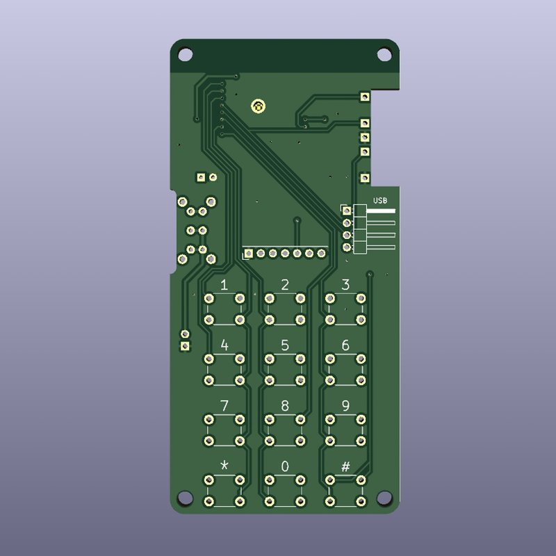
Step1 Main board
Solder the small parts first. There are 3 resistors and 1 capacitor.
小さな部品を先にはんだ付けします。抵抗3個とキャパシタ1個です。

Next, solder the ESP32C3. At this time, solder each one point diagonally first to prevent it from floating. GND allows heat to escape easily, so solder carefully.
つぎにESP32C3をはんだ付けします。この際に対角に1点を先に止めて浮きを防止します。GNDは熱が逃げやすいので、丁寧にはんだ付けします

Eliminate flux with a flux cleaner.
フラックスクリーナーでフラックスを排除します。

Solder the pin (2P), L pin (4P), and switch as shown in the photo. Then install the spacer. The front side is 6mm and the back side is 10mm.
写真の様に、ESP32が付いてる面に、ピン(2P)、Lピン(4p)、スイッチをはんだ付けします。その後でスペーサーを取り付けます。表側が6mm、裏側が10mmです。

Solder the encoder with the encoder board. Add some solder to the contact points with the main board.
エンコーダーをエンコーダー基板にはんだ付けします。メイン基板との接点にもはんだを盛っておきます。
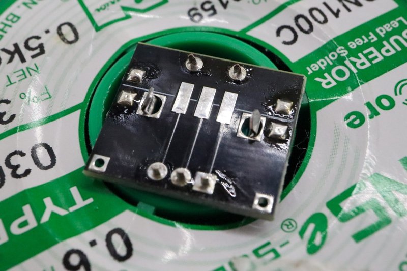
Temporarily attach the encoder board to the main board. Use a file to file down the sides of the encoder board so that it is level with the spacer.
エンコーダ基板をメイン基板に仮止めします。エンコーダー基板がスペーサーと水平になるように、やすり等で側面を削ります。

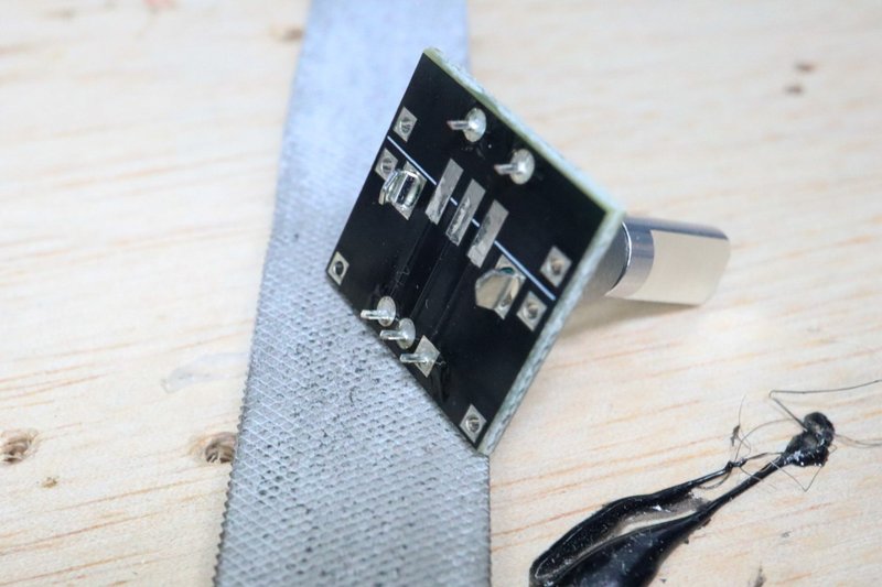
Apply solder to the contacts on the main board side. Then solder the boards together. Install the encoder board at right angles to the main board. Alternate soldering to ensure even thermal stress.
メイン基板側の接点にはんだを塗布します。その後で、基板同士をはんだ付けします。エンコーダー基板はメイン基板に直角になるように取り付けます。熱応力が均等になるように交互にはんだ付けを行います。

Install the tact switch. Then do the soldering. The switch may float, so first solder only one point on each switch, make sure there is no floating, and then solder the remaining three points.
タクトスイッチを取り付けます。その後にはんだ付けをします。スイッチが浮く場合があるので、最初に各1点だけはんだ付けをしてから浮きがないことを確認して、残りの3点をはんだ付けしてください。

Finally, attach the LCD. Install the LCD screen so that it is parallel to the board.
Check with a tester that there are no short circuits and that the resistor is properly installed.
最後にLCDを取り付けます。LCDの画面が基板と平行になるように取り付けてください。
テスターで短絡がないこと、抵抗が適切に取り付けられていることを確認してください。

Step2 Battery Board
Install the USB-C battery charging board.
USB-Cバッテリー充電基板を取り付けます。
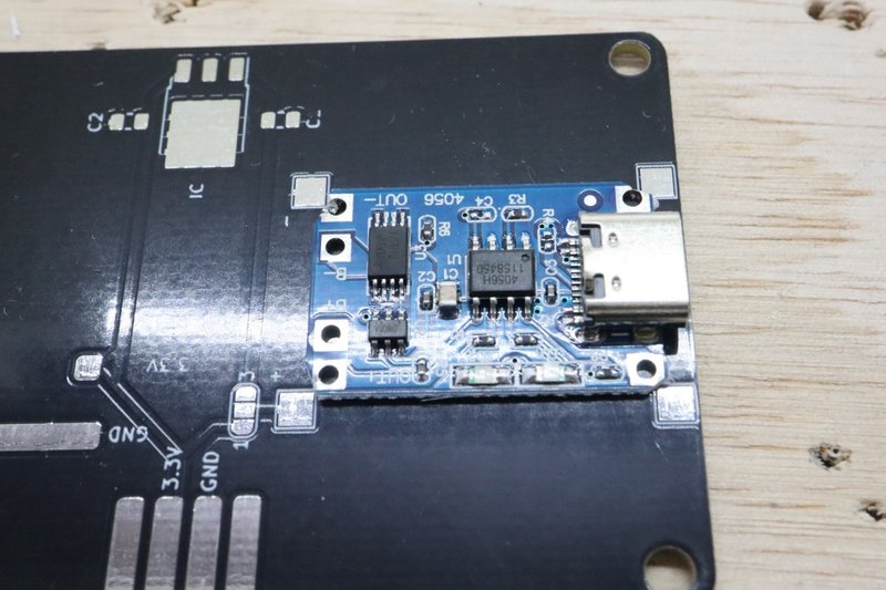
Connect between both contacts using electric wires (not included). (Planned to improve in the future)
電線(員数外)等を使って、接点間を結びます。(将来改良予定)

Solder the battery connection cable.
バッテリー接続用のケーブルをはんだ付けします。

Protect the cable so that it will not short circuit even if it comes off.
ケーブルが外れても短絡しない様に養生します。

Disconnect terminals 1 and 2 using a cutter, etc. After confirming that it is disconnected with a tester, connect between 2 and 3.
*When connecting 1-2 : Supplies 3.0-4.2V to the main board (No LDO required)
*When connecting 2-3 : Supplies 3.0-3.3V to the main board
カッター等で端子1-2間を断絶します。テスターで断絶されていることを確認後に、2-3間を接続します。
*1-2を接続時:3.0-4.2Vをメイン基板に供給(LDO不要)
*2-3を接続時:3.0-3.3Vをメイン基板に供給

Install the LDO and capacitor. Install a 2.2uf capacitor on the right side of the photo, and a 0.33uf capacitor (substitute 0.39uf, etc.) on the left side of the photo.
LDOとキャパシタを取り付けます。キャパシタは写真右に2.2uf、写真左に0.33uf(0.39uf等で代用)を取り付けます。

Connect the battery. Please make sure the polarity matches before connecting. (At this point, the socket in top side of photo is not installed)
Please make sure 3.2-3.3V is supplied between GND-3.3V with the tester.
<Important!!>
Incorrect polarity may cause overheating or fire.
バッテリーを接続します。接続前に極性が一致していることを確認してください。(この時点では写真上側のソケットは未取り付けです)
テスターでGND-3.3V間に3.2-3.3Vが供給されていることを確認してください。
<重要!!>
極性を間違えると加熱・発火の恐れがあります。

Fix the battery in a position where it will not interfere with the main board.
<Important!!> If the battery is damaged, there is a risk of overheating and ignition.
メイン基板と干渉しない位置にバッテリーを固定します。
<重要!!> バッテリーが傷つくと加熱・発火の恐れがあります。

Step3 Assemble
Insert the socket into the pin and connect the main board and battery board. At this time, spread the pin contacts slightly inward, outward, outward, and inward.
ソケットをピンに挿して、メイン基板とバッテリー基板を接続します。この時にピンの接点は内―外―外―内に少し広げておいてください。

Solder the socket pins.
ソケットのピンをはんだ付けします。

Create a USB connector.
USBコネクタを作成します。

Insert the socket and connector into each other and secure them by soldering.
ソケットとコネクタを互いに差し込んでハンダ付けをして固定します。

Insert it into the L pin of the main board. The encoder side becomes GND.<Important!!> If you connect it in the opposite direction, the 5V on the PC side will be connected to the GND of the WiFI Throttle. Please work carefully.
メイン基板のLピンに差し込みます。エンコーダ側がGNDになります。
<重要!>反対向きに繋ぐと、PC側の5VがWiFI ThrottleのGNDに接続されます。慎重に作業をしてください。

Turn on the power while pushing the encoder. After confirming that the LCD is white and that the main unit is not heating, smoking, or smelling, connect it to the PC using the USB cable. If your PC does not recognize the ESP32C, please rotate the encoder. If the driver is not installed, please install it.
Upload the sketch using the Arudino IDE. I will not explain how to use the Arudino IDE here.
エンコーダを押し込みながら電源をいれます。LCDが白色であり、本体に加熱・発煙・異臭がないことを確認したら、USBケーブルでPCと接続します。PCがESP32Cを認識しない場合は、エンコーダを回転させてください。ドライバが未導入の場合はドライバを導入してください。
-> 参考ページ
Arudino IDEを使用して、スケッチを書き込んでください。Arudino IDEの使用方法はここでは割愛します。
-> 参考ページ

Attach the case, cap and knob to complete.
If you have difficulty pressing the button, use a file to roughly file down the bottom of the cap by approximately 0.5 mm.
ケース、キャップとノブを取り付けて完成です。
ボタンを押し込み難いときは、キャップの底面をやすりで0.5mmほど粗く削ってください。

4.FAQ
PC does not recognize the ESP32C3.
Must be in writable mode. You need to turn on the power while pushing the encoder button. In writable mode, the screen will be white.
Pins are shared by USB input and encoder input. Try rotating the encoder to see if it is recognized.
Even when connected to a PC, power is obtained from the battery. Make sure it can be powered by the battery.
It doesn't recognize the button when I press it.
Try removing the cap and pressing it. If you can press it easily in this state, the cap is inserted deeply into the tact switch. Roughly file the bottom of the cap to about 0.5mm.
ESP32C3をPCが認識しない。
書き込み可能なモードにする必要があります。エンコーダを押し込みながら電源をいれる必要があります。書き込み可能なモードでは画面は白色になります。
USB入力とエンコーダ入力でピンを共用しています。エンコーダを回転させて認識するか試してください。
PCと接続時も電源はバッテリーから得ています。バッテリーから給電できるようにしてください。
ボタンを押しても認識しない。
キャップを外して押してみてください。その状態で容易に押せる場合は、キャップがタクトスイッチに深く差さっています。キャップの底面をやすりで0.5mmほど粗く削ってください。
この記事が気に入ったらサポートをしてみませんか?