
MapleSimで超簡単な油圧モデルを作ってみた#6(2リンクを動かす油圧モデル)

#5の記事では図1に示す1つのリンクを1つのシリンダで上下させる機構を油圧で動作させるシステムのモデリングをしました。今回はリンクの増やして2リンク機構にして油圧で動かしてみましょう。

作成する2リンク機構
図2は今回作成する2リンク機構です。
第一リンクの先端部分に第2リンクを取り付け、さらに第2リンクの先端部分にロボットハンドなどのアタッチメントを想定した重りを取り付けています。第2リンクを動かすシリンダ図2に示すように第1リンク上と第2リンクの先端部分の逆側の端とをつないでいます。シリンダを伸ばすと第2リンクは手前に動き、シリンダを縮めると第2リンクは遠のく側へ動きます。

モデルの改造
図3は改造後のモデルです。
詳細はこの記事の最後に貼り付けてあるモデル自体を実際に見てもらうとして、ここでは簡単にどんな改造をしたかを紹介します。
図3の左側は#5の記事で作成した1リンク機構の油圧モデルとほとんど同じです。黒枠部分をコピぺーして右側に貼り付けます。左側の青枠部分は第2リンクを動かすシリンダの根元側を取り付けるためのものです。第1リンクの重心からの位置関係を設定して、第2リンクのシリンダの根本の回転機構ブロックに結線します。
また、右側の黒枠内の赤枠は第2リンクの先端部分の重りです。
さらに、もう一度左側の黒枠に戻って、赤矢印を見てください。この部分は#5の記事ではタンクに戻していた部分ですが、今回は第2リンクを動かすシリンダを制御するバルブの入力部分に結線します。こうすることで第1リンクを動かすバルブで使わなかった油を第2リンクを動かすバルブで使うことができます。こんな回路をタンデム回路なんて言ったりします。
そして右側の黒枠の下にある赤枠はチャンバーです。第1リンクを動かすバルブと第2リンクを動かすバルブの間なのでチャンバーを設置します。

なお、第1リンク、第2リンクの重心の質量や、リンクやシリンダの設置ポジション、第1リンクを動かすバルブと第2リンクを動かすバルブの間なのでチャンバーの設定、各バルブのスプールに対する開口面積の詳しい設定は記事の最後に貼り付けてあるモデルを見てください。
スプールの時系列入力設定
今回のモデルではバルブのスプールの時系列入力を補間テーブル(Lookup Table 1D)と時間ブロックで作成します。図4の2つの赤枠部分が時間ブロックと補間テーブルブロックです。補間テーブルの設定値は図5に示します。

図5のA列は時間[s]です。0[s]から22[s]まで時刻と、その時の値をB列とC列に記載しています。B列は第1リンクを動かすバルブの時系列値で、C列は第2リンクを動かすのバルブの時系列値です。補間テーブルブロックの設定で何番目の列を使うかを選択できる設定がありますので、同じcsvファイルに時系列データを設定しておいて、設定によって使い分けすることができます。
設定した時系列データを見てみましょう。最初に第1リンクのシリンダを伸ばし、次に第2リンクのシリンダを伸ばします。さらに今度は第2リンクのシリンダを縮め、最後に第1リンクのシリンダを縮めています。

シミュレーション結果
それではシミュレーション結果を見てみましょう。
リンク動作のアニメーションを図6に示しています。
初期設定が悪いようで、最初にガタガタっとなってから第1リンクが上昇し始めていますね。その後は期待どおりの動きになっているように見えます。
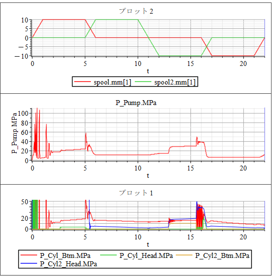
時系列の波形も見てみましょう(図7)。
1行目はスプールの時系列データです。
2列目はポンプ圧の時系列データ、3列目は2つのシリンダボトムとヘッドの圧力データです。
最初に第1リンクがガタガタっとなっているところで油圧が振動していますね。それ以外にも気になるところがあります。
シリンダ2が動き出す5.5[s]くらいまでシリンダ2のヘッド圧が相当高くなっていることがわかります。シリンダ2を動かすバルブがオープンすることでヘッド側に封入されている圧が一気に抜けていいます。最初に第1リンクがガタガタっとなった際にシリンダ2のヘッド側が圧縮されてしまったようです。シリンダ2が縮む側でストロークエンドなのでリンクの動きには影響していませんが、実際にこんな高圧になってしまっていたらシリンダホースはパンクしてしまいます。なのでこんなことが起きた場合にもパンクさせないように安全弁(リリーフバルブ)をシリンダポートに取り付けることが多いように思います。
他にもこの油圧システムには、油圧のプロの目からするとシステム上不足している機能(機器)が結構あります。油圧のプロの目で見てしまうと、シミュレーションなどしなくても頭の中でのシミュレーションで課題を発見することができますが、勉強中の皆さんはシミュレーションをすることで、この油圧システムの課題を検討してみると、かなり良い勉強になると思いますので、チャレンジしてみてください。
【English】
In article #5, we modeled a system that uses hydraulic pressure to operate the mechanism shown in Figure 1, in which one link is moved up and down by one cylinder. In this article, we will increase the number of links to make it a two-link mechanism and move it hydraulically.
2-Link Mechanism to be Created
Figure 2 shows the two-link mechanism to be created in this article. A second link is attached to the end of the first link, and a weight is attached to the end of the second link, which is intended to be an attachment such as a robot hand. The cylinder that moves the second link connects the top of the first link to the opposite end of the tip of the second link, as shown in Figure 2. When the cylinder is extended, the second link moves closer to the front, and when the cylinder is retracted, the second link moves farther away.
Model Modifications
Figure 3 shows the model after modification. For more details, you can actually see the model itself pasted at the end of this article, but here is a brief description of what modifications were made. The left side of Figure 3 is almost the same as the hydraulic model of the one-link mechanism created in article #5. Copy and paste the black-bordered part to the right side. The blue-bordered part on the left side is for attaching the root side of the cylinder that moves the second link. Set the positional relationship from the center of gravity of the first link, and connect the wires to the rotating mechanism block at the root of the cylinder of the second link. The red-bordered part within the black-bordered part on the right side is the weight for the tip of the second link. Additionally, go back to the black-bordered part on the left side again and look at the red arrow. This is the part that was returned to the tank in article #5, but this time it is tied to the input of the valve that controls the cylinder that moves the second link. In this way, the oil not used by the valve that moves the first link can be used by the valve that moves the second link. This kind of circuit is called a tandem circuit. The red-bordered part under the black-bordered part on the right is the chamber. The chamber is located between the valve that moves the first link and the valve that moves the second link.
Note that the mass of the center of gravity of the first and second links, the position of the links and cylinders, the setting of the chamber because it is between the valve that moves the first link and the valve that moves the second link, and the detailed setting of the opening area to the spool of each valve are shown in the model pasted at the end of this article.
Time Series Input Settings for Spools
In this model, the time series input for the valve spool is created with an interpolation table (Lookup Table 1D) and a time block. The two red framed areas in Figure 4 are the time block and the interpolation table block. The settings for the interpolation table are shown in Figure 5.
Column A in Figure 5 is the time [s]. columns B and C list the time from 0[s] to 22[s] and the value at that time. column B is the time series value of the valve that moves the first link and column C is for the second link. There is a setting in the interpolation table block settings that allows you to select what column to use, so you can set up time series data in the same csv file and use them differently depending on the settings. Let's look at the time series data we have set up. First the cylinder of the first link is extended, then the cylinder of the second link is extended. Then the cylinder of the second link is retracted, and finally the cylinder of the first link is retracted.
Simulation
Now let's look at the simulation results. The animation of the link operation is shown in Figure 6. It seems that the initial settings are not very good, and the first link starts to rise after the first rattling. After that, the motion appears to be as expected.
Let's also look at the time series waveforms (Figure 7): the first row is the spool time series data; the second row is the pump pressure; the third row is the pressure data for the two cylinder bottoms and heads. You can see the oil pressure oscillating at the first link where the first link is rattling. There are other areas of concern as well. You can see that the cylinder 2 head pressure is quite high until about 5.5[s], when cylinder 2 starts to move. When the valve that moves cylinder 2 opens, the pressure sealed in the head side is released at once. It seems that the head side of cylinder 2 was compressed when the first link rattled at first. Since cylinder 2 is at the end of its stroke on the side where it contracts, it has no effect on the movement of the linkage, but if the pressure had actually reached such a high level, the cylinder hose would have been punctured. Therefore, a safety valve (relief valve) is often installed at the cylinder port to prevent a puncture in the event of such a situation. There are many other functions (devices) in the hydraulic system that are lacking from the viewpoint of a hydraulic professional. However, if you are studying, it would be a good learning experience to examine the issues of this hydraulic system through simulation, so please give it a try. Please try it.
【Sample Model】
Created by MapleSim 2023
この記事が気に入ったらサポートをしてみませんか?