
MapleSimで超簡単な油圧モデルを作ってみた#3(2つの可変開口オリフィスによる流量分配)

前回作成した固定容量ポンプと可変オリフィス、そしてリリーフバルブの油圧モデルを今回は、さらに改造して油圧回路での流量分配をしてみます。
2つの可変オリフォスを設置
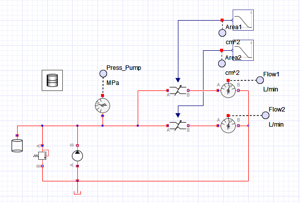
前回作成した油圧回路をベースに図1に示すように可変オリフィスブロックをもうひとつ追加して、2つ可変オリフィスブロックを並列に設置します。
上側の可変オリフィスを「1」、下側の可変オリフィスを「2」とします。
2つの可変オリフィスの開口面積を図2(上側)のように時系列で変化させてみると、それぞれのオリフィスを通過する流量は図2(下側)のように変化します。オリフィスを並列に設置することで開口面積比によって流量を分配できることがわかります。
この特性を使うことで、油圧シリンダや油圧モータの動きをコントロールすることができます。次回の記事では油圧シリンダを追加して動かしてみたいと思います。

【English】
The hydraulic model of a fixed displacement pump, variable orifice, and relief valve created in the last issue will now be further modified to distribute the flow in the hydraulic circuit.
Two Variable Orifice Installed
Based on the hydraulic circuit created previously, add another variable orifice block as shown in Figure 1, and install two variable orifice blocks in parallel. The upper variable orifice is designated "1" and the lower variable orifice is designated "2.
When the opening areas of the two variable orifices are varied in time series as shown in Figure 2 (upper side), the flow rate through each orifice changes as shown in Figure 2 (lower side). It can be seen that by installing orifices in parallel, the flow rate can be distributed according to the aperture area ratio.
This characteristic can be used to control the movement of hydraulic cylinders and hydraulic motors. In my next article, I will add a hydraulic cylinder and move it.
【Sample Model】
Created by MapleSim 2023
この記事が気に入ったらサポートをしてみませんか?