RealityCaptureを用いた遺構オルソ画像の作成

これまでMetashapeを使用してオルソ画像を作成していましたが、RealityCaptureがほぼ無償化したことから、移行できるか検証のため、まずは基本の平面、断面のオルソ画像作成からやってみました。備忘録のためにメモしておきます。
なお、今回は手順のみを検証したため、細かなパラメータ等は未確認です。
0. 準備
インストール方法はたくさん情報があるので割愛します。
0.1 言語の設定
[WORKFLOW]→[Settings]→[UI Language]→[Japanese]
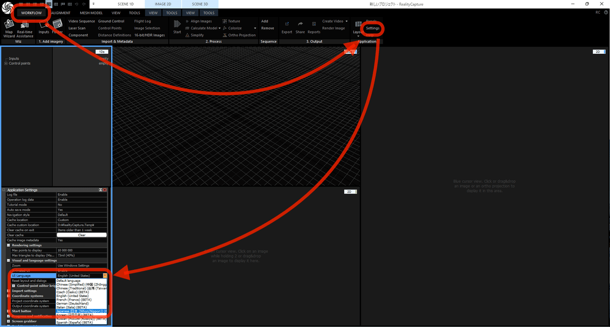
0.2 座標系の設定
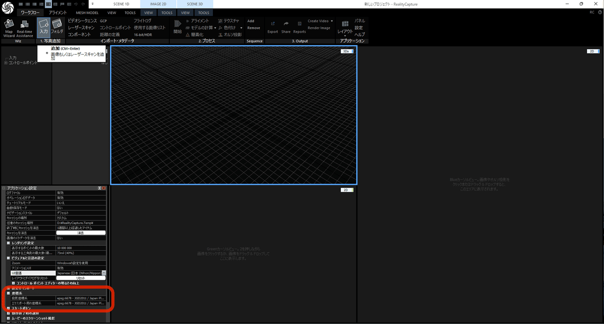
1. 平面図オルソ画像の作成
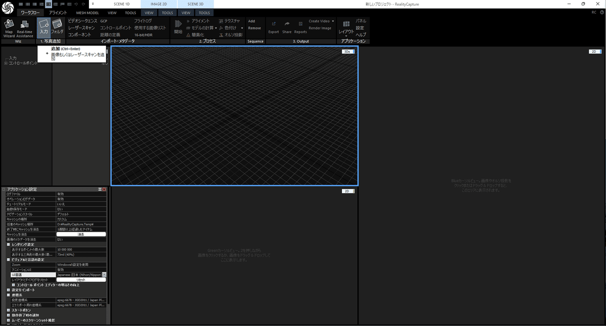
1.1 写真の読み込み
[ワークフロー]→[入力]→[追加]
写真を選択して[開く]
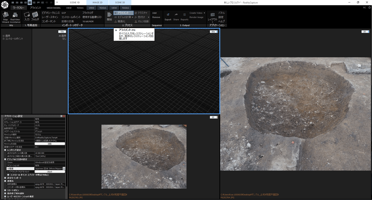
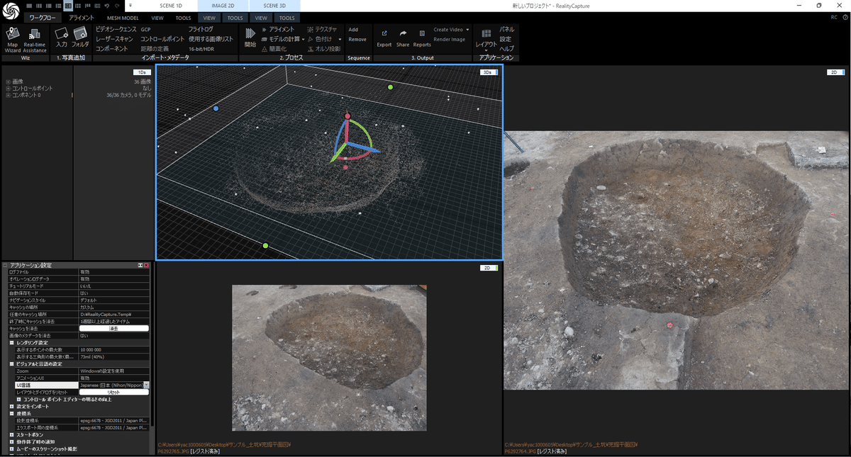
1.2 アライメント
[ワークフロー]→[アライメント]
しばらく待つと点群が表示されます。
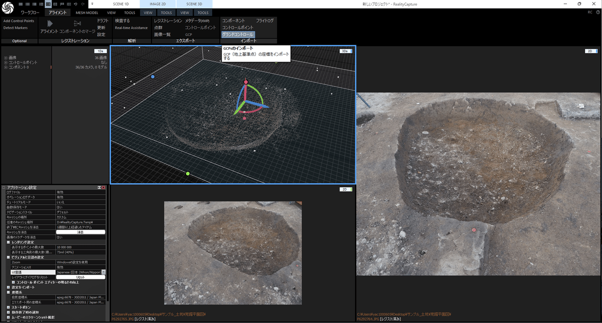
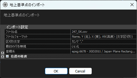
1.3 座標値の読み込み
[アライメント]→[グランドコントロール]
座標値が記録されたCSVファイルを読み込みます。
CSVファイルは「点名、X座標、Y座標、標高」の列の順で作成しておきます。
1.4 コントロールポイントの配置
画面左のコントロールポイント(CP)のリストから写真の点の位置にドラッグ&ドロップします。
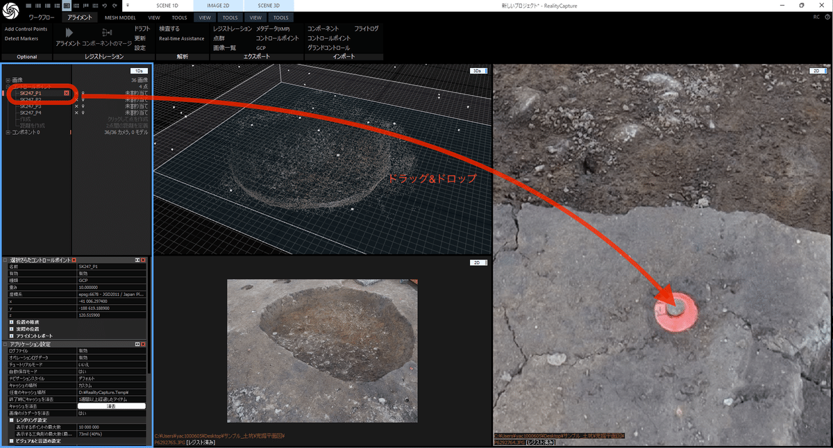
落とした点をクリックすると拡大表示され、位置の微調整ができます。
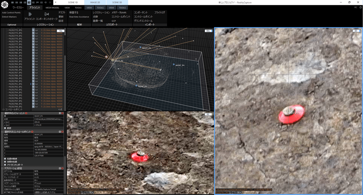
全ての点を配置します。途中で何度か[アライメント]すると精度が上がっていくような気がします。
MetaShapeではtabキーとPageUp,Downキーでサクサクと位置調整できましたが、RCでは同じ方法があるか未確認です。
アライメントする度にコンポーネント(MetaShapeのチャンクのようなもの?)が増えるので、不要なコンポーネントは削除します。
位置を微調整、またはCP右側の緑の十字アイコンをクリックすると位置が確定されるようです。
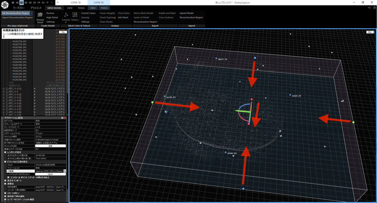
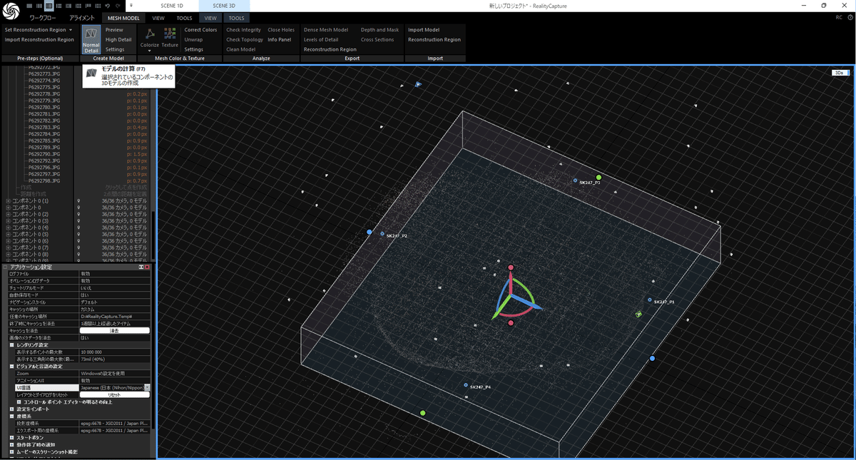
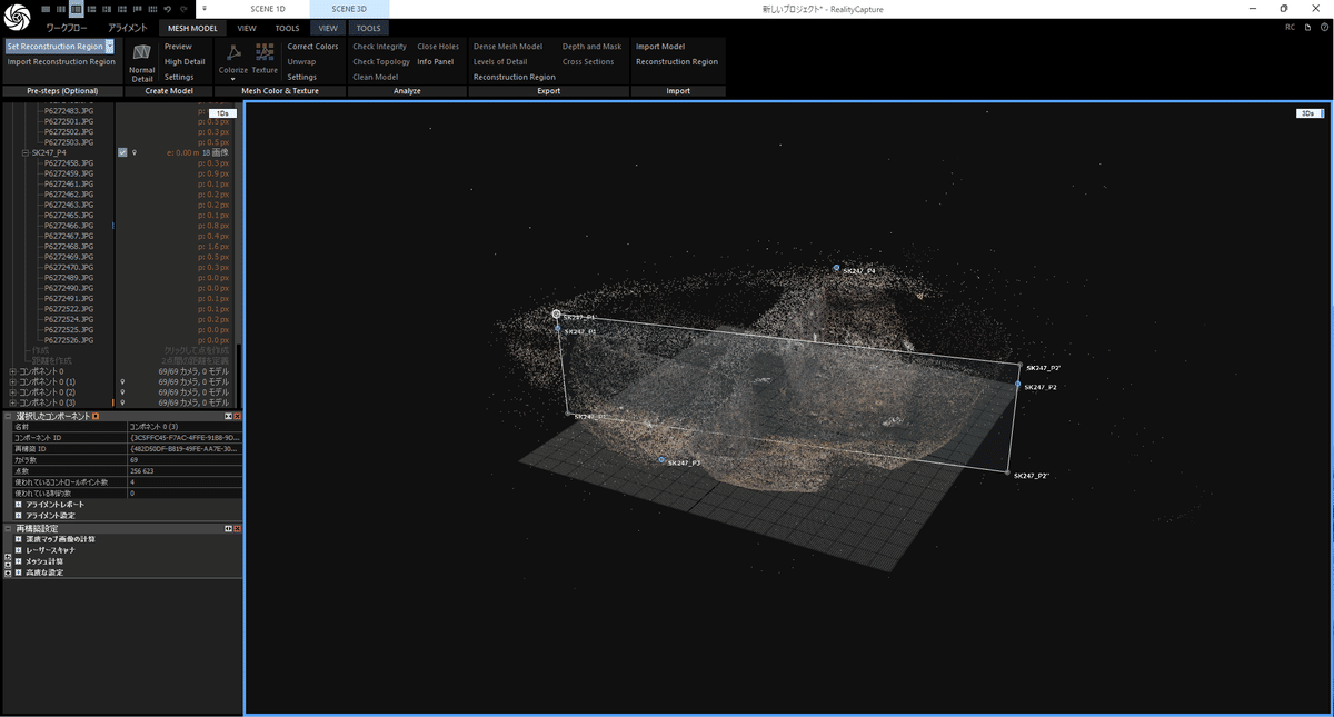
1.5 再構築領域のセット
計算時間を短縮するために範囲を設定します。
[MESH MODEL]→[Set Reconstruction Region]
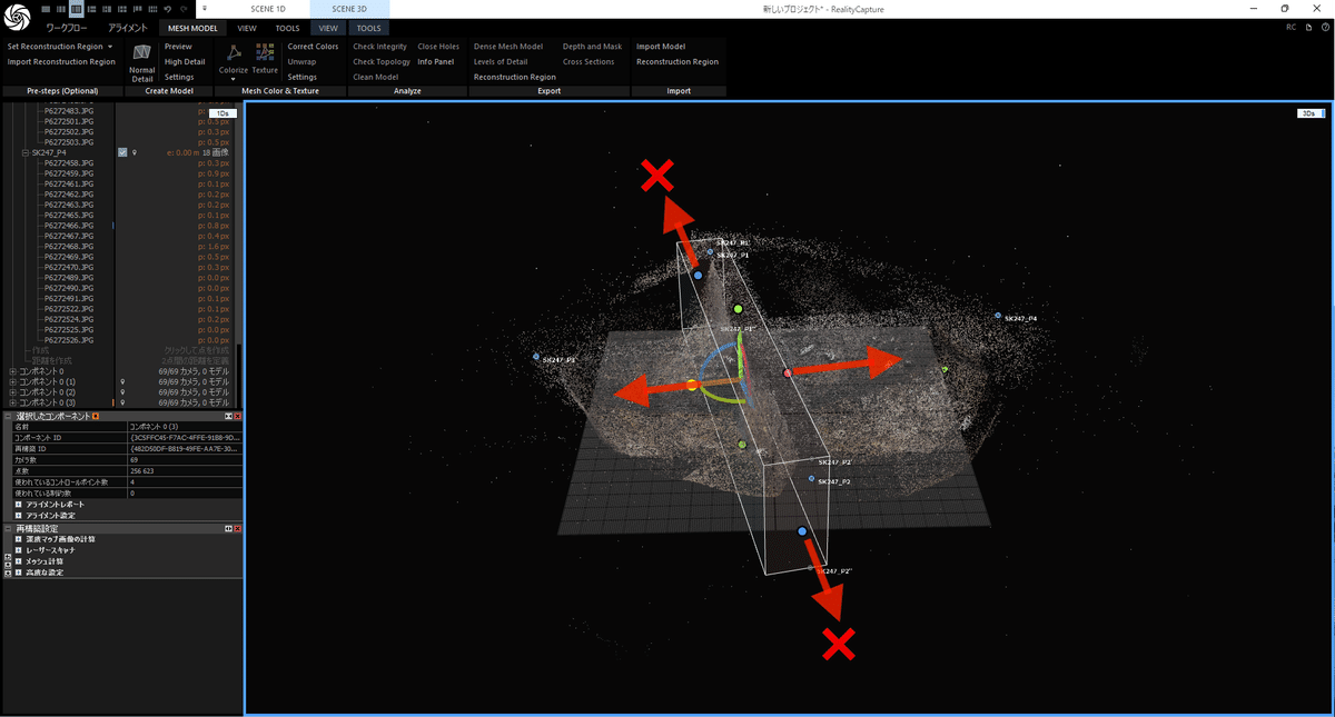
上下左右の点をドラッグして範囲を設定します。
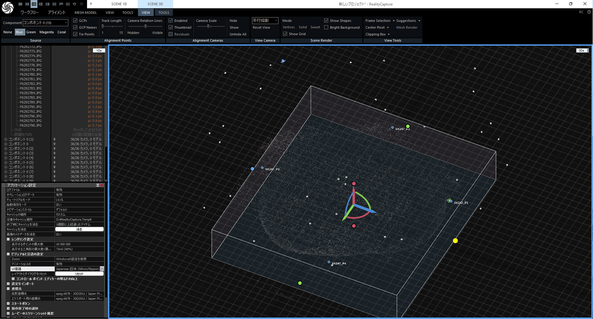
[VIEW]→[view Camera]で遠近法、並行投影、視点の設定ができます。
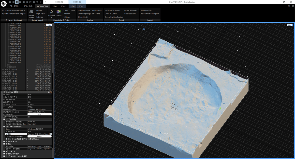
1.6 モデルの計算
[MESH MODEL]→[Nomal Detail]でメッシュを構築します。
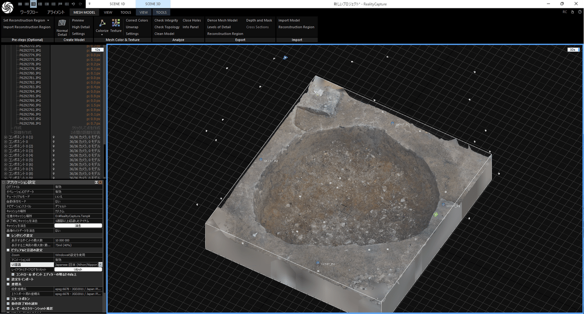
[MESH MODEL]→[Texture]でテクスチャを構築します。
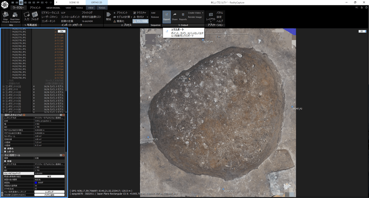
1.7 オルソ画像の作成
[ワークフロー]→[オルソ投影]
オレンジ枠で投影したい面を選択します。
左側のオルソ投影ツールで[オルソのピクセルサイズ]を変更して[推定]をクリックすると出力される画像のサイズが表示されます。
適切な解像度を設定し、[レンダリング]をクリックします。
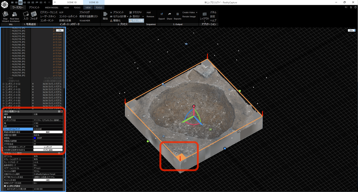
オルソ画像が作成されました。
[ワークフロー]→[Export]→[Color Orthographics Projection]で画像を出力します。

出力したオルソ画像はQGIS等で使用できます。
2 土層断面図オルソ画像の作成
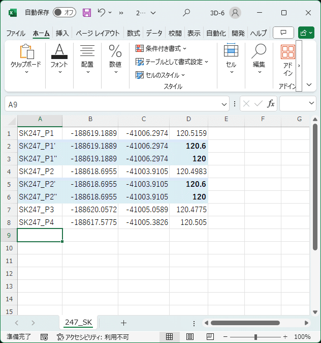
2.1 断面図用CSVファイルの準備
断面図のオルソ画像投影面を設定するためのコントロールポイントを追加したCSVファイルを作成します。
左右のセクションポイント(下図ではP1とP2)を2つコピーし、標高をキリのいい数字に変更します。数字はそれぞれ土層断面の最高地点より高く、最低地点より低くしておきます。
2.2 写真の読み込みとアライメント
平面図と同じなので割愛します。
2.1で作成したP1',P1''等はアライメント時には無視します。
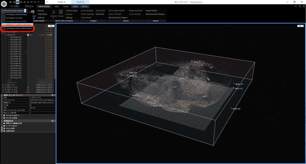
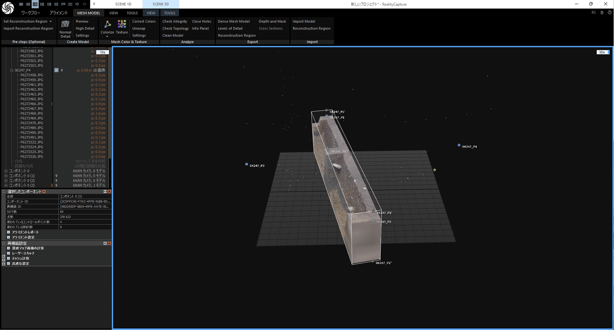
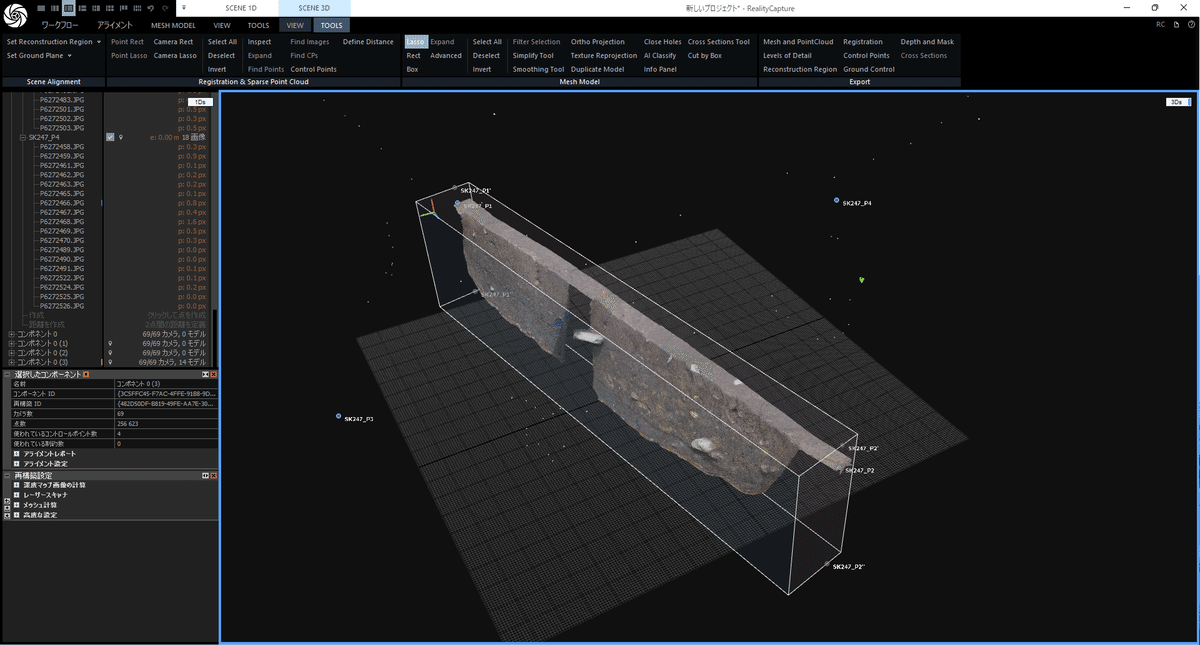
2.3 再構築領域のセット
[MESH MODEL]→[Set Reconstruction Region]→[Set Region from Control Points]
P1'→P2'→P2''の順にクリックし、断面を含む再構築領域を設定します。
断面の前後方向に拡張して断面全体が入るように設定します。その時、断面の上下、左右方向は動かさないようにします。
2.4 メッシュの構築とテクスチャ作成
平面図と同じなので割愛します。
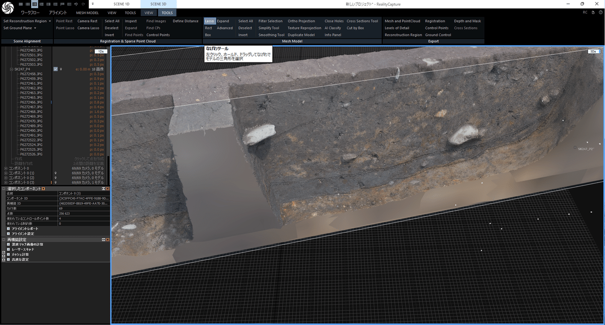
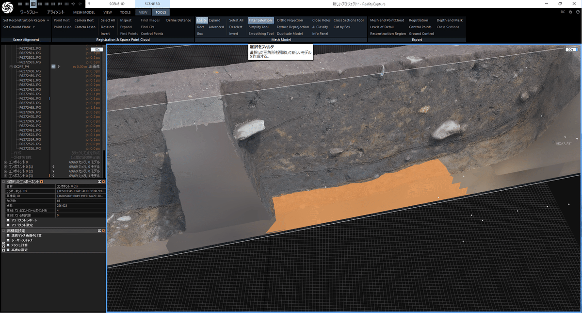
2.5 不要部分の削除
[TOOLS]→[Lasso](なげなわツール)で不要な部分(正面から見て断面にかかる壁面等)を選択します。
[Filter Selection]で選択部分を削除します。
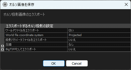
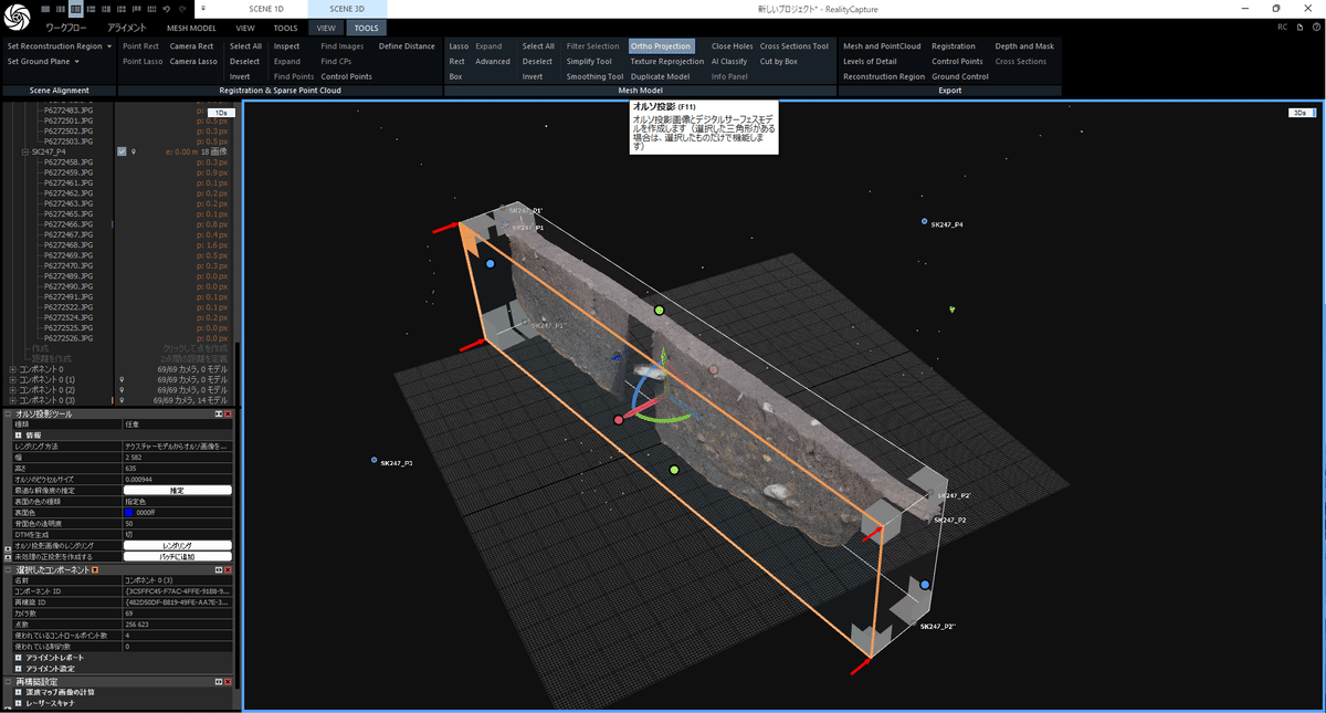
2.6 オルソ画像の作成・出力
平面図と同じですが、投影面を土層の正面に設定し、枠の左上をクリックします。
また、座標系はlocalにしておきます。
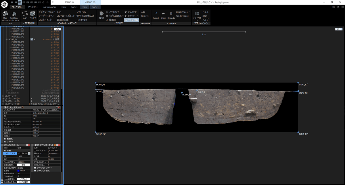
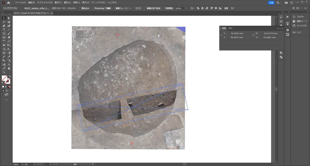
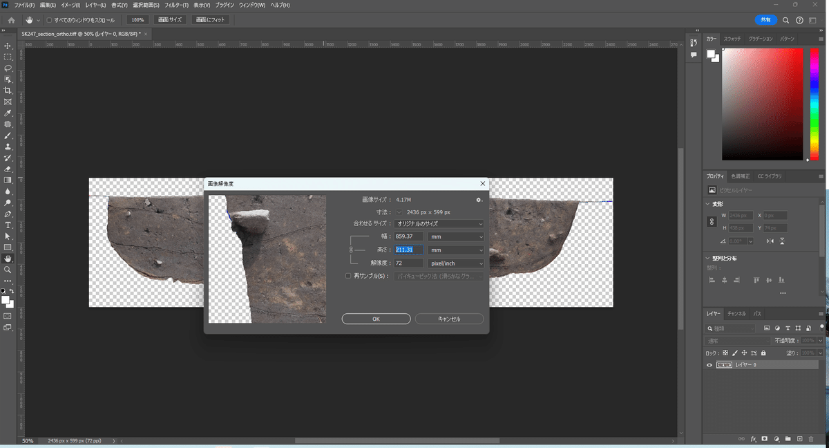
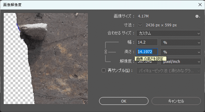
2.7 オルソ画像の縮尺調整
出力したオルソ画像をPhotoshop等で開きます。
画像の上辺と下辺が2.1で設定した標高値になっているので、それを元に縮尺を調整します。
例では120.6-120=600mm、画像の高さが211.31mmなので、1/20にする場合、600/211.31/20=14.1972%です。
2.8 平面図と断面図のサイズ確認
QGIS等で縮尺を調整した平面と、2.7で縮尺を調整した断面をIllustrator等に配置して大きさが合っていることを確認します。