Three.js r149 で Buffer Geometry つかってみるテストその2

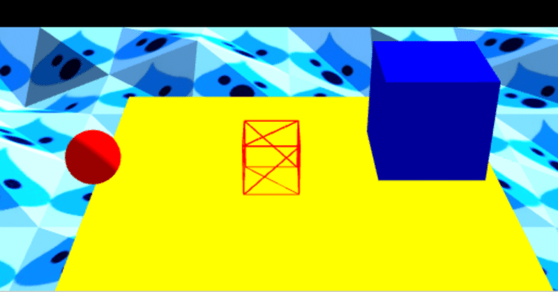
その1からのつづきです。 その1の最後で使い始めたBuffer Geometryと物理演算の連携を保ちつつ、Buffer Geometryでどこまでできるかを実験しています。 実験で、自分がわかりやすい・認識しやすい基準でテクスチャを表示させているので、扉絵のように風変わりなテクスチャが多いかもですw。
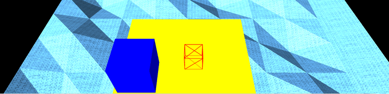
Three.js r149 Buffer Geometry Test11 Textured Heightfield Test01
Three.js r149 Buffer Geometry Test11 Textured Heightfield Test01

まず単純に自分が理解しやすいように平面の板に星のテクスチャを貼り付けています。 まずは一枚板です。
Three.js r149 Buffer Geometry Test12 Textured Heightfield Test02
Three.js r149 Buffer Geometry Test12 Textured Heightfield Test02
配列で指定していたはずなので、次は2x2の4枚板です。
Three.js r149 Buffer Geometry Test13 Textured Heightfield Test03
Three.js r149 Buffer Geometry Test13 Textured Heightfield Test03

3x3の9枚板です。
Three.js r149 Buffer Geometry Test14 Textured Heightfield Test04
Three.js r149 Buffer Geometry Test14 Textured Heightfield Test04
Test13から何を変更したのか忘れましたw。
Three.js r149 Buffer Geometry Test15 Textured Heightfield Test05
Three.js r149 Buffer Geometry Test15 Textured Heightfield Test05
配列の数を増やして、元にしたサンプルプログラムの形に少し近づけてデコボコした地面にしています。
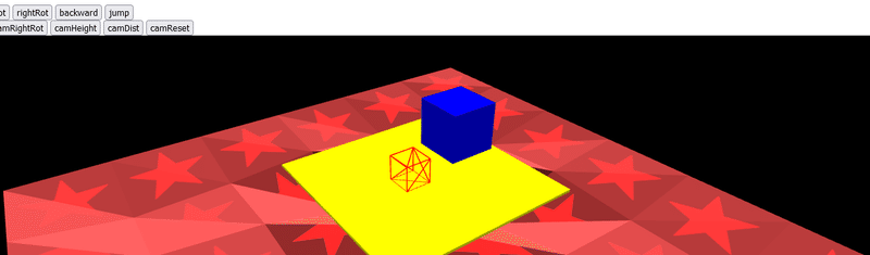
Three.js r149 Buffer Geometry Test16 Textured Heightfield Test06
Three.js r149 Buffer Geometry Test16 Textured Heightfield Test06

影か色を濃くして、地面のデコボコを彫り?を深くしたんかな?たぶん。 時間が経ってもう忘れかけているところも多いので、プログラムのキャプチャ画像を見ながらテキトー書いてるかもです。
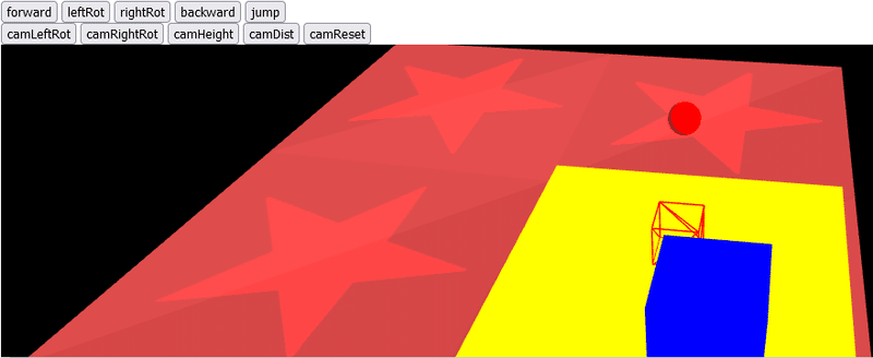
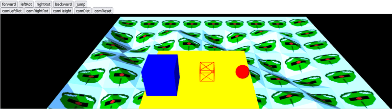
Three.js r149 Buffer Geometry Test17 Textured Heightfield Test07
Three.js r149 Buffer Geometry Test17 Textured Heightfield Test07
スライム風画像をテクスチャとして貼り付けてみたら、小さい単位になりすぎて水色の地面になったものです。
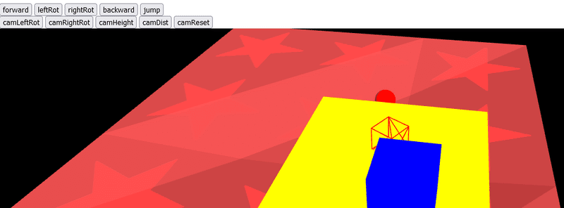
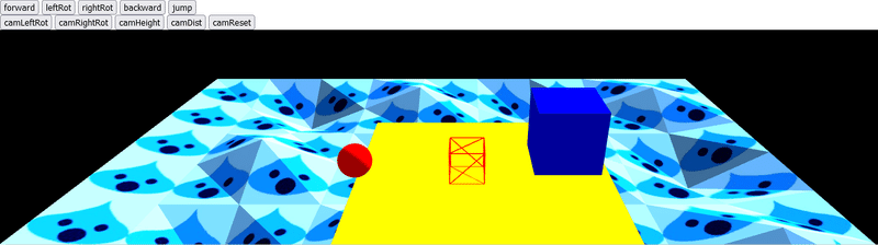
CodePen Home Three.js r149 Buffer Geometry Test18 Textured Heightfield Test08
CodePen Home Three.js r149 Buffer Geometry Test18 Textured Heightfield Test08
設定を変えて、テクスチャの絵もザク風絵にしてみたものです。 わかりやすい大きさになりました。
CodePen Home Three.js r149 Buffer Geometry Test19 Textured Heightfield Test09
CodePen Home Three.js r149 Buffer Geometry Test19 Textured Heightfield Test09
最後にスライム風テクスチャも大きく見えるように作りなおしてみました。 このnoteの扉絵にしているものです。 少しだけBuffer Geometryとテクスチャの貼り付けの制御ができるようになった気がします。
またこの「 Buffer Geometry Test19 」では「 Buffer Geometry Test18 」からカメラの制御の方法を大幅に修正しました。 それまでの、(自分がプログラムできる範囲内でしかカメラ位置を計算・設定できなかったために)カメラが初期状態の位置から操作Boxに対して反対側に回りこむようになっていたものを修正しました。 反対側に回りこまないようにするために、いくつかパラメーターを真逆にする必要などが生じて、これまで直せずにいたものが修正できました。 自分の中でのプログラム的にはなかなか発展的なことだったので、最後にその部分のコードを抜き出したものを貼り付けておきます。
次回
修正後カメラ位置計算プログラム抜き出し
カメラ位置計算の部分を修正したプログラムの抜き出しです。 最初にココで作成したカメラ位置計算プログラムの大々的な修正となりました。 後で参照用に貼り付けておきます(後で実際にBabylon.jsでの作業中に参照して役立ってくれました)。
CodePen Home Three.js r149 Buffer Geometry Test19 Textured Heightfield Test09
の function animate() 関数の抜き出しとなります。 カメラを操作Boxの真後ろに移動させる、メインの部分は if ( camResetButtonOn ) のif文の中となります。
function animate() {

    requestAnimationFrame(animate);

    // Cannon.jsの物理空間の時間を進める
    world.fixedStep();

    delta = clock.getDelta();

    let rotateAngle = Math.PI / 2 * delta;

    inputVelocity.set(0, 0, 0);


    // 「leftRot」ボタン押下時処理
    if(leftRotButtonOn) {

        yawObject.rotation.y += rotateAngle;

    }

    // 「rightRot」ボタン押下時処理
    if(rightRotButtonOn) {

        yawObject.rotation.y -= rotateAngle;

    }

    // 「forward」ボタン押下時処理
    if(forwardButtonOn) {

        //inputVelocity.z = velocityFactor * delta * 50;
        inputVelocity.z = -velocityFactor * delta * 50;

    }

    // 「backward」ボタン押下時処理
    if(backwardButtonOn) {

        //inputVelocity.z = -velocityFactor * delta * 50;
        inputVelocity.z = velocityFactor * delta * 50;

    }


    // ★カメラ操作の計算・設定 Start ★
    // カメラ左回転ボタン押下時
    if ( camLeftRotButtonOn ) {
        targetRot = targetRot - 2;
    // カメラ右回転ボタン押下時
    } else if ( camRightRotButtonOn ) {
        targetRot = targetRot + 2;
    }


    // 「camReset」ボタン押下時処理
    //
    // カメラを操作オブジェクトの背後(真後ろ)に配置したいが、直接計算してカメラのtargetRotを設定する方法がわからないので
    // 一旦、操作オブジェクト&カメラのベクトル&クォータニオンによりカメラ位置計算後に、
    // クォータニオン → 弧度法 → 度数法 → 調整いろいろ、と変換してカメラ位置を設定
    //
    // テキトーな理解でのテキトーコード作成のためこの方法での位置計算が一般的かは疑わしい。。。
    if ( camResetButtonOn ) {

        let cameraEuler = new THREE.Euler();
        let cameraQuaternion = new THREE.Quaternion();
        cameraEuler.y = viewWireBox.rotation.y;

        cameraEuler.order = 'XYZ';
        cameraQuaternion.setFromEuler(cameraEuler);


        // カメラ設定
        // カメラの位置をベクトルとクォータニオンで設定

        // Z軸方向のベクトルを作成(進行方向のベクトルを作成)
        let directionVec = new THREE.Vector3( 0, 0, 1 );

        // Z軸方向のベクトル(進行方向のベクトル)にカメラの角度の元となるクォータニオンを適応
        directionVec.applyQuaternion(cameraQuaternion);

        // カメラの距離をベクトル的に掛け算
        directionVec.multiplyScalar(cameraDistance);

        // .negate()関数を使用してカメラの位置が操作Boxの背後となるように設定
        //let cameraDirection = directionVec.clone();
        let cameraDirection = directionVec.clone().negate();

        // 操作Boxの位置をベクトルで取得
        let viewWireBoxPosition = new THREE.Vector3( viewWireBox.position.x, viewWireBox.position.y, viewWireBox.position.z );

        // カメラの高さを表すベクトルを取得
        let camHeightVec = new THREE.Vector3( 0, cameraHeight, 0 );


        // 操作Boxの位置ベクトル + カメラの(角度を含む)位置ベクトル + カメラの高さベクトル
        // → 現在のカメラの位置ベクトルを演算
        const cameraPosition =  cameraDirection.add(viewWireBoxPosition).add(camHeightVec);


        // カメラの位置ベクトルをカメラに設定
        camera.position.copy(cameraPosition);
        // カメラが操作Boxの方を見るように設定
        camera.lookAt(new THREE.Vector3( viewWireBox.position.x, viewWireBox.position.y, viewWireBox.position.z ));


        let temp = new THREE.Euler().setFromQuaternion( cameraQuaternion, 'XYZ' );

        targetRot = THREE.MathUtils.radToDeg(temp.y)


        // viewWireBoxのクォータニオンの値(viewWireBox.quaternion.y)によりカメラの回転設定を調整

        // quaternion.y がマイナス値の場合は、quaternion.y が -0.7より大きい場合、-0.7以下の場合で処理を分ける
        // quaternion.y が0以上の場合は、quaternion.y が 0.7より小さい場合、0.7以上の場合で処理を分ける

        // ↑以上、以下、より小さい、より大きい、の境界線の設定基準はあいまい。。。(自分がよく理解できていないため)

        // targetRot = targetRot + 180 の値設定によるカメラ方向が↑上記の場合分けによる状態で異なるためこの処理を行っている
        // なぜこのような状態になるのかはほぼ理解できず、とりあえず判定できる状況にあわせていろいろ設定したもの


        // quaternion.y がマイナス値の場合(操作オブジェクトが1、3、5、、、回転目はマイナス値となる、たぶん。。。)
        if(0 > viewWireBox.quaternion.y) {

            // quaternion.y が -0.7より大きい場合
            if(-0.7 < viewWireBox.quaternion.y) {
                targetRot = targetRot;
                //
                // ↑360となった値は一回転分となるので360の分はなくす
                //targetRot = targetRot + 360;
                //
                // ↑元のコード(Fork元の前回のコード)からカメラの回転を180ずらしたので同じように180追加
                //targetRot = targetRot + 180;

            // quaternion.y が -0.7以下の場合
            } else {
                targetRot = 180 - targetRot;
                //targetRot = 360 - targetRot + 180;
                //targetRot = 360 - targetRot;

            }

        // quaternion.y が0以上の場合(操作オブジェクトが2、4、6、、、回転目はマイナス値となる、たぶん。。。)
        } else {

            // quaternion.y が 0.7より小さい場合
            if(0.7 > viewWireBox.quaternion.y) {
                targetRot = targetRot;
                //targetRot = targetRot + 360;
                //targetRot = targetRot + 180;

            // quaternion.y が 0.7以上の場合
            } else {
                targetRot = 180 - targetRot;
                //targetRot = 360 - targetRot + 180;
                //targetRot = 360 - targetRot;

            }

        }


        // コメントアウト中
        // コード中に操作オブジェクトやカメラのパラメータ確認用に使用conslole
        //let quaternioValToSee = viewWireBox.quaternion;
        //console.log("quaternioValToSee  x: " + quaternioValToSee.x + " y: " + quaternioValToSee.y + " z: " + quaternioValToSee.z + " w: " +quaternioValToSee.w);

        //console.log("viewWireBox.rotation.y:  " + viewWireBox.rotation.y);

        //console.log("temp.y:  " + temp.y);

        //console.log("targetRot:  " + targetRot);

    }


    //rot += 0.5; // 毎フレーム角度を0.5度ずつ足していく
    // イージングの公式を用いて滑らかにする
    // 値 += (目標値 - 現在の値) * 減速値
    rot += (targetRot - rot) * 0.05;

    // 角度に応じてカメラの位置を設定
    camera.position.x = viewWireBox.position.x + cameraDistance * Math.sin(rot * Math.PI / 180);
    camera.position.z = viewWireBox.position.z + cameraDistance * Math.cos(rot * Math.PI / 180);
    // 操作対象3Dオブジェクトを見つめる
    camera.lookAt(new THREE.Vector3( viewWireBox.position.x, viewWireBox.position.y, viewWireBox.position.z ));
    // ★カメラ操作の計算・設定 End ★


    // Convert velocity to world coordinates
    // 自分の理解では、
    // ボタン操作による、操作オブジェクトのy軸回転情報、進行方向ベクトル、のプラマイ(+・-)計算後
    // 操作オブジェクトのy軸回転情報をクォータニオンに変換して
    // そのクォータニオンを進行方向ベクトルへ適応させ、操作オブジェクトの進行方向&速度を表すベクトルを作成
    //euler.x = pitchObject.rotation.x;
    euler.y = yawObject.rotation.y;
    euler.order = 'XYZ';
    quaternion.setFromEuler(euler);
    inputVelocity.applyQuaternion(quaternion)


    // 上記で作成した操作オブジェクトの進行方向&速度を表すベクトルを操作オブジェクトへ適応
    phyWireBox.velocity.x += inputVelocity.x
    phyWireBox.velocity.z += inputVelocity.z


    // Cannon.jsの物理空間の演算によるSphereの位置・回転をThree.jsによる見た目に反映
    viewSphere.position.copy(phySphere.position);
    viewSphere.quaternion.copy(phySphere.quaternion);


    // Cannon.jsの物理空間の演算によるBoxの位置・回転をThree.jsによる見た目に反映
    viewBox.position.copy(phyBox.position);
    viewBox.quaternion.copy(phyBox.quaternion);


    // Cannon.jsの物理空間の演算によるワイヤーフレームBoxの位置・回転をThree.jsによる見た目に反映
    viewWireBox.position.copy(phyWireBox.position);
    //viewWireBox.quaternion.copy(phyWireBox.quaternion);
    viewWireBox.quaternion.copy(quaternion);


    // Three.js レンダリング
    renderer.render(scene, camera);

}この記事が気に入ったらサポートをしてみませんか?