モータを角度を決めて回す

ステッピングモータの制御
ステッピングモータは角度を指定して回転させることが出来るモータです。角度の精度が良いので機械制御などに使われているモータです。このモータを回すためにはモータドライバを使う必要があります。
モータドライバに指令を送るマイコン+モータドライバという構成でモータを回します。
ステッピングモータは秋月電子やオリエンタルモータで扱っています。ステッピングモータは2相タイプ、5相タイプがあります。一般的なのは2相タイプです。2相タイプにも6線式ユニポーラタイプと4線式バイポーラタイプの2種類があります。多くのドライバが4線式バイポーラに対応しています。
ステッピングモータは1回転(360度)を200等分した1.8度が基本の1ステップになります。ドライバによりこの基本ステップを1/2, 1/4, 1/8, 1/16, 1/32と分割したマイクロステップ駆動が可能です。ドライバによりマイクロステップの分割数が決まります。またモータにどこまで電流を流せるのか決まってきます。
オープン制御とクローズ制御
ステッピングモータはパルスで回転角度を制御します。実際に回転したかどうかは監視しないオープン制御になっています。負荷が高い時などパルス通りに動かない事を「脱調」と呼びます。
サーボモータは出力軸の角度を測定して指定された角度まで回転するように制御しています。これをクローズド制御と呼びます。このためには出力軸に回転角度を測定するためのセンサー(ロータリーエンコーダ)が必要になります。
出力の高いサーボモータはアンプと呼ばれる制御部分も入れると高価になります。今回はステッピングモータを使い安価にサーボモータと同じ事をやってみます。
ドライバの選定
ステッピングモータドライバのドライバは様々な種類があります。今回は大電流が流せ電圧も高め、マイクロステップ分割数が高いものを選びました。
Pololu 36v4 高出力ステッピングモータドライバ
最大で6Aまで電流を流せます。マイクロステップも1/256まで対応しています。Arduino用のライブラリがあるのも選定のポイントです。SPI通信で電流、マイクロステップ数の設定を行えます。回転には回転方向とステップ入力で2ポートを使います。
ロータリーエンコーダの選定
ロータリーエンコーダは様々なタイプがありますが、分解能が高く非接触で使えるタイプを選択しました。
AS5048A搭載 磁気エンコーダモジュール
このエンコーダは8mmの磁石の回転角度をICで検出します。分解能は14bit(16384)もあります。1回転(360度)を16384等分して検出可能です。0.0219度の分解能になります。そこまで必要なのか?という感じです。中心軸が多少ずれても使えるのがこのエンコーダの売りのポイントです。
Arduinoのライブラリも以下にあります。こちらもSPI通信で角度の読み取りが可能です。
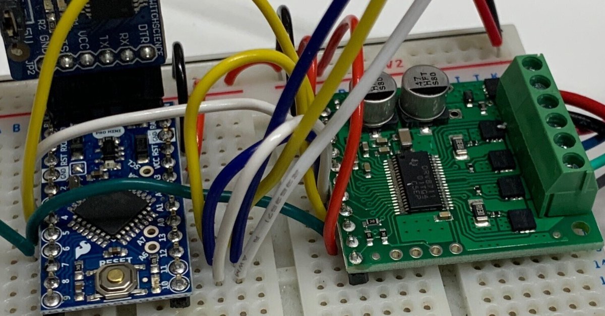
配線
Arduino Pro miniを使った配線は次の図のようになります。
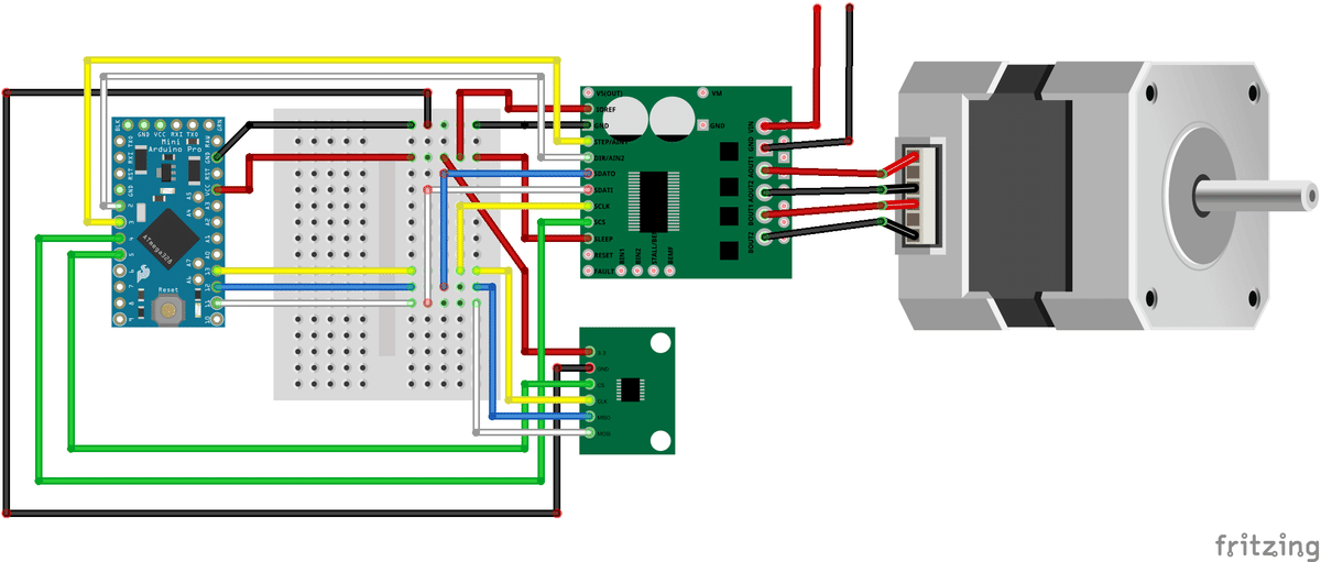
モータドライバから上に伸びている赤と黒の線にモータ用の電源を接続します。12V〜50Vまでの電源が使えます。モータに合わせて選定してください。普通のサイズのモータであれば24Vぐらいで良いと思います。
Arduino Pro miniの3.3Vの電源はPCからのシリアル変換器からの給電になります。以下の動画ではモータを回し、エンコーダで値を読み取りArduino IDEのシリアルコンソールに値を表示しています。
ロータリーエンコーダは次のように取り付けています。基板を固定する部分。モータの軸の先端に直径の8mmの磁石を取り付ける部分があります。磁石は8mmの穴に圧入して固定しています。
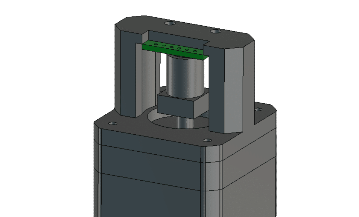
Fusion360のモデルのリンクはこちらです。42mm角のモータの場合です。
Arduinoのコードは次のとおりです。
上記ライブラリのサンプルコードを参考にしています。
#include <SPI.h>
#include <HighPowerStepperDriver.h>
#include <AS5048A.h>

AS5048A angleSensor(5, false);//AS5048のCS Pin=5

const uint8_t DirPin = 2;
const uint8_t StepPin = 3;
const uint8_t CSPin = 4;//DRV8711のCS Pin

const uint16_t StepPeriodUs = 500;//回転速度を決めるためのuSec wait

HighPowerStepperDriver sd;

void setup()
{
  Serial.begin(19200);

  SPI.begin();
  sd.setChipSelectPin(CSPin);

  // Drive the STEP and DIR pins low initially.
  pinMode(StepPin, OUTPUT);
  digitalWrite(StepPin, LOW);
  pinMode(DirPin, OUTPUT);
  digitalWrite(DirPin, LOW);

  // Give the driver some time to power up.
  delay(1);

  // Reset the driver to its default settings and clear latched status
  // conditions.
  sd.resetSettings();
  sd.clearStatus();

  // Select auto mixed decay.  TI's DRV8711 documentation recommends this mode
  // for most applications, and we find that it usually works well.
  sd.setDecayMode(HPSDDecayMode::AutoMixed);

  sd.setCurrentMilliamps36v4(400); // Set the current limit.

  // Set the number of microsteps that correspond to one full step.
  sd.setStepMode(HPSDStepMode::MicroStep32);

  sd.enableDriver();// Enable the motor outputs.

  pinMode(4, OUTPUT);
  pinMode(5, OUTPUT);
  pinMode(4, LOW);
  pinMode(5, LOW);
  angleSensor.begin();
}

void loop()
{
  Serial.println("=========");

  setDirection(0);
  for (unsigned int x = 0; x < 3200; x++)
  {
    step();
    delayMicroseconds(StepPeriodUs);

    float val = angleSensor.getRotationInDegrees();
    if ((x % 200) == 0) {//200回に1回だけSerialにprintする
      //Serial.print("deg: ");
      Serial.println(val);
    }
  }

  delay(300);// Wait for 300 ms.

  setDirection(1);
  for (unsigned int x = 0; x < 3200; x++)
  {
    step();
    delayMicroseconds(StepPeriodUs);

    float val = angleSensor.getRotationInDegrees();
    if ((x % 200) == 0) {//200回に1回だけSerialにprintする
      //Serial.print("deg: ");
      Serial.println(val);
    }
  }

  delay(300); // Wait for 300 ms.
}

// Sends a pulse on the STEP pin to tell the driver to take one step, and also
//delays to control the speed of the motor.
void step()
{
  // The STEP minimum high pulse width is 1.9 microseconds.
  digitalWrite(StepPin, HIGH);
  delayMicroseconds(3);
  digitalWrite(StepPin, LOW);
  delayMicroseconds(3);
}

// Writes a high or low value to the direction pin to specify what direction to
// turn the motor.
void setDirection(bool dir)
{
  // The STEP pin must not change for at least 200 nanoseconds before and after
  // changing the DIR pin.
  delayMicroseconds(1);
  digitalWrite(DirPin, dir);
  delayMicroseconds(1);
}
角度を指定して回転させるコードは次のとおりです。Arduino IDEのシリアルコンソールに角度を半角英数で入力します。enterキーで送信されます。回転した後に角度を読み取ってずれがある場合にはその角度まで回ります。
#include <SPI.h>
#include <HighPowerStepperDriver.h>
#include <AS5048A.h>


AS5048A angleSensor(5, false);

const uint8_t DirPin = 2;
const uint8_t StepPin = 3;
const uint8_t CSPin = 4;

const uint16_t StepPeriodUs = 50;

float motorStep;

HighPowerStepperDriver sd;

String inputString = "";         // a String to hold incoming data
bool stringComplete = false;  // whether the string is complete
float targetDeg;//motor set deg 移動さきの角度
float currentDeg;//motor deg モータの現在の角度

void setup()
{
  Serial.begin(19200);

  SPI.begin();
  sd.setChipSelectPin(CSPin);

  // Drive the STEP and DIR pins low initially.
  pinMode(StepPin, OUTPUT);
  digitalWrite(StepPin, LOW);
  pinMode(DirPin, OUTPUT);
  digitalWrite(DirPin, LOW);

  delay(1);// Give the driver some time to power up.

  // Reset the driver to its default settings and clear latched status
  // conditions.
  sd.resetSettings();
  sd.clearStatus();

  // Select auto mixed decay.  TI's DRV8711 documentation recommends this mode
  // for most applications, and we find that it usually works well.
  sd.setDecayMode(HPSDDecayMode::AutoMixed);

  sd.setCurrentMilliamps36v4(400);// Set the current limit.

  // Set the number of microsteps that correspond to one full step.
  sd.setStepMode(HPSDStepMode::MicroStep32);
  motorStep = 1.8 / 32.0;

  sd.enableDriver();// Enable the motor outputs.

  pinMode(4, OUTPUT);
  pinMode(5, OUTPUT);
  pinMode(4, LOW);
  pinMode(5, LOW);
  angleSensor.begin();

  inputString.reserve(200);

  targetDeg = 0.0;

  //pinMode(5, LOW);
  currentDeg = angleSensor.getRotationInDegrees();
  Serial.print("currentDeg:" );
  Serial.println(currentDeg);
  targetDeg = currentDeg;
}


//int i = 0;

void loop()
{
  //enterキーを押されたときの数値を読み取る
  if (stringComplete) {
    targetDeg = inputString.toFloat();
    Serial.print("targetDeg:");
    Serial.println(targetDeg);
    inputString = "";// clear the string:
    stringComplete = false;
  }

  currentDeg = angleSensor.getRotationInDegrees();

  float d = targetDeg - currentDeg;//現在位置と移動位置の差を求める
  if (abs(d) > (motorStep * 8)) {//8step以上の時には移動を開始
    int degStep = abs(d) / motorStep;//移動するステップ数を求める
    Serial.println(degStep);
    if (d < 0.0) {//回転方向の設定
      setDirection(0);
    } else {
      setDirection(1);
    }
    float delayTime = 60.0;//初期回転速度
    for (int i = 0 ; i < degStep ; i++) {//回転の実行
      step();
      delayMicroseconds(delayTime);
      if (i< 100) delayTime -=0.5;//加速の処理
      if (i > degStep-100) delayTime +=10.0;//減速の処理
    }
  }

}


void serialEvent() {
  while (Serial.available()) {
    // get the new byte:
    char inChar = (char)Serial.read();
    // add it to the inputString:
    inputString += inChar;
    // if the incoming character is a newline, set a flag so the main loop can
    // do something about it:
    if (inChar == '\n') {
      stringComplete = true;
    }
  }
}


// Sends a pulse on the STEP pin to tell the driver to take one step, and also
//delays to control the speed of the motor.
void step()
{
  // The STEP minimum high pulse width is 1.9 microseconds.
  digitalWrite(StepPin, HIGH);
  delayMicroseconds(3);
  digitalWrite(StepPin, LOW);
  delayMicroseconds(3);
}

// Writes a high or low value to the direction pin to specify what direction to
// turn the motor.
void setDirection(bool dir)
{
  // The STEP pin must not change for at least 200 nanoseconds before and after
  // changing the DIR pin.
  delayMicroseconds(1);
  digitalWrite(DirPin, dir);
  delayMicroseconds(1);
}
0や360を指定すると連続回転になります。停止条件、初期速度は電流やモータの負荷に合わせて調整が必要です。停止時にオーバーランするとそこから指定角度まで回ることになり連続回転することになります。
この記事が気に入ったらサポートをしてみませんか?