15.レジスタを実装して分周回路付きPWM発振回路を作る

ここではCPU側に対しての一般的なインターフェースとレジスタを実装するとともに分周回路を持ったPWM発振機能を持つ回路作成について触れていきます。
静電写真系のプリンタエンジンにおいて、そのハードウエア制御で本機能はとても重要です。(高圧制御とか)
問題
以下の回路モジュール(分周・PWM発振)を作成してください。
<レジスタ解説書(分周>
アドレス 属性 解説 データ
0x00 リードライト 分周値設定 下位2bit
(データ”00” 1/4分周)
(データ”01” 1/8分周)
(データ”10” 1/16分周)
(データその他 1/4分周)
#0x は16進数表記

<レジスタ解説書(PWM>
アドレス 属性 解説 データ
0x00 リードライト 1周期期間 8bit
0x01 リードライト Lレベル期間 8bit
0x02 リードライト 発振ONOFF 1bit
(データ’0’ 発振停止)
(データ’1’ 発振)
#1周期期間・・分周の値による
(例:最小単位1:1/4分周ならば4clk)
(例:最小単位1:1/8分周ならば8clk)
(例:最小単位1:1/16分周ならば16clk)
# Lレベル期間・・分周の値による
(例:最小単位1:1/4分周ならば4clk)
(例:最小単位1:1/8分周ならば8clk)
(例:最小単位1:1/16分周ならば16clk)
さてどう作る?
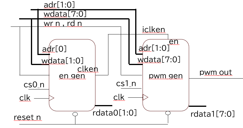
シンボル図・回路図にある通り、分周回路(en_gen)から出力されるiclkenをPWM発振回路(pwm_gen)に入れることで、PWM発振の時間の粒度(時間の最小単位)を変更できるようにします。こうすることで、PWM発振回路を変えずに対応レンジ(1周期時間等)を広げたりすることができるようになります。
VHDLで書いてみる
まず分周回路のen_genです。フリーランカウンタを作って、カウンタの値が
”0011”の時は1/4分周(4clkに1回clkenをH)
"0111"の時は1/8分周(8clkに1回clkenをH)
"1111"の時は1/16分周(16clkに1回clkenをH)
を出すようになっています。最終的にどれを使うかは最下段のprocess文の通り、レジスタの値によってセレクトされます。
library IEEE;
use IEEE.STD_LOGIC_1164.ALL;
use IEEE.STD_LOGIC_ARITH.ALL;
use IEEE.STD_LOGIC_UNSIGNED.ALL;

entity en_gen is
	port (	clk 	:in std_logic;
			reset_n :in std_logic;
			adr		:in std_logic;
			cs_n	:in std_logic;
			wr_n	:in std_logic;
			rd_n	:in std_logic;
			wdata	:in std_logic_vector(1 downto 0);
			rdata	:out std_logic_vector(1 downto 0);
			clken	:out std_logic);
end en_gen;

architecture rtl of en_gen is
	signal icnt					:std_logic_vector(3 downto 0);
	signal i4en , i8en , i16en	:std_logic;
	signal isel					:std_logic_vector(1 downto 0);
begin


	process(clk,reset_n)
	begin
		if reset_n = '0' then
			isel <= (others => '0');
		elsif rising_edge(clk) then
			if adr='0' and cs_n ='0' and wr_n = '0' then
				isel <= wdata;
			end if;
		end if;
	end process;

	process(clk,reset_n)
	begin
		if reset_n = '0' then
			rdata <= (others => '0');
		elsif rising_edge(clk) then
			if adr='0' and cs_n ='0' and rd_n = '0' then
				rdata <= isel;
			end if;
		end if;
	end process;

	process(clk,reset_n)
	begin
		if reset_n = '0' then
			icnt <= (others => '0');
		elsif rising_edge(clk) then
			icnt <= icnt + '1';
		end if;
	end process;

	process(icnt)
	begin
		if icnt(1 downto 0) = "11" then
			i4en <= '1';
		else i4en <= '0';
		end if;
	end process;

	process(icnt)
	begin
		if icnt(2 downto 0) = "111" then
			i8en <= '1';
		else i8en <= '0';
		end if;
	end process;

	process(icnt)
	begin
		if icnt = "1111" then
			i16en <= '1';
		else i16en <= '0';
		end if;
	end process;

	process(isel,i4en,i8en,i16en)
	begin
		case isel is
			when "00" => clken <= i4en;
			when "01" => clken <= i8en;
			when "10" => clken <= i16en;
			when others => clken <= i4en;
		end case;
	end process;

end rtl;
シミュレーション結果
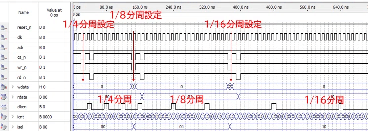
次にPWM発振回路のpwm_genです。1~4目のprocess文がレジスタ関連、5~7個目のprocess文でPWMを生成しています。
library IEEE;
use IEEE.STD_LOGIC_1164.ALL;
use IEEE.STD_LOGIC_ARITH.ALL;
use IEEE.STD_LOGIC_UNSIGNED.ALL;

entity pwm_gen is
	port (	clk 	:in std_logic;
			reset_n :in std_logic;
			adr		:in std_logic_vector(1 downto 0);
			cs_n	:in std_logic;
			wr_n	:in std_logic;
			rd_n	:in std_logic;
			wdata	:in std_logic_vector(7 downto 0);
			rdata	:out std_logic_vector(7 downto 0);
			en		:in std_logic;
			pwm_out	:out std_logic);
end pwm_gen;

architecture rtl of pwm_gen is
	signal iperiod,iltime,ipcnt		:std_logic_vector(7 downto 0);
	signal iset,ipcmp,ipwm_out		:std_logic;

begin


	process(clk,reset_n)
	begin
		if reset_n = '0' then
			iperiod <= (others => '0');
		elsif rising_edge(clk) then
			if adr="00" and cs_n ='0' and wr_n = '0' then
				iperiod <= wdata;
			end if;
		end if;
	end process;

	process(clk,reset_n)
	begin
		if reset_n = '0' then
			iltime <= (others => '0');
		elsif rising_edge(clk) then
			if adr="01" and cs_n ='0' and wr_n = '0' then
				iltime <= wdata;
			end if;
		end if;
	end process;

	process(clk,reset_n)
	begin
		if reset_n = '0' then
			iset <= '0';
		elsif rising_edge(clk) then
			if adr="10" and cs_n ='0' and wr_n = '0' then
				iset <= wdata(0);
			end if;
		end if;
	end process;

	process(clk,reset_n)
	begin
		if reset_n = '0' then
			rdata <= (others => '0');
		elsif rising_edge(clk) then
			if adr="00" and cs_n ='0' and rd_n = '0' then
				rdata <= iperiod;
			elsif adr="01" and cs_n ='0' and rd_n = '0' then
				rdata <= iltime;
			elsif adr="10" and cs_n ='0' and rd_n = '0' then
				rdata <= "0000000"&iset;

			end if;
		end if;
	end process;

--
	process(clk,reset_n)
	begin
		if reset_n = '0' then
			ipcnt <= "00000001";
		elsif rising_edge(clk) then
			if en ='1' and (iset = '0' or ipcmp = '1') then
				ipcnt <= "00000001";
			elsif en = '1' then
				ipcnt <= ipcnt + '1';
			end if;
		end if;
	end process;

	process(ipcnt,iperiod)
	begin
		if ipcnt = iperiod then
			ipcmp <= '1';
		else ipcmp <= '0';
		end if;
	end process;


	process(ipcnt,iltime)
	begin
		if ipcnt <= iltime then
			ipwm_out <= '0';
		else ipwm_out <= '1';
		end if;
	end process;

	pwm_out <= ipwm_out and iset;

end rtl;
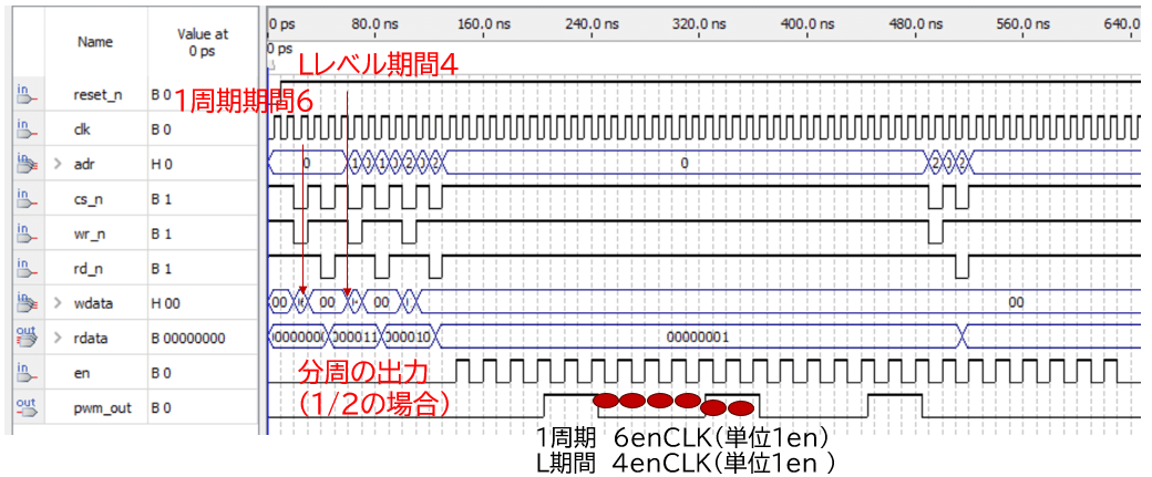
シミュレーション結果
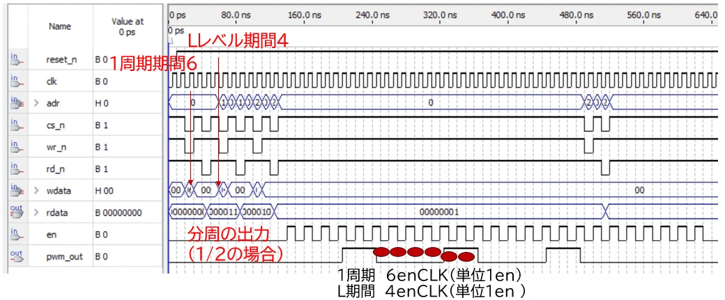
次に上記2つの分周・PWM発振回路を接続するTOP階層(pwm_top)のVHDLコードを示します。シンボル図・回路図に従って各モジュールに接続するだけです。
library IEEE;
use IEEE.STD_LOGIC_1164.ALL;
use IEEE.STD_LOGIC_ARITH.ALL;
use IEEE.STD_LOGIC_UNSIGNED.ALL;

entity pwm_top is
    Port ( 	clk 	: in STD_LOGIC;
           	reset_n : in STD_LOGIC;
           	cs0_n	: in STD_LOGIC;
           	cs1_n	: in STD_LOGIC;
           	adr		: in STD_LOGIC_VECTOR (1 downto 0);
           	wr_n	: in STD_LOGIC;
           	rd_n	: in STD_LOGIC;
           	wdata	: in STD_LOGIC_VECTOR (7 downto 0);
           	rdata0	: out STD_LOGIC_VECTOR (1 downto 0);
           	rdata1  : out STD_LOGIC_VECTOR (7 downto 0);
           	pwm_out : out  STD_LOGIC);
end pwm_top;

architecture rtl of pwm_top is
    signal iclken	: STD_LOGIC;

    component en_gen
    port (	clk 	:in std_logic;
			reset_n :in std_logic;
			adr		:in std_logic;
			cs_n	:in std_logic;
			wr_n	:in std_logic;
			rd_n	:in std_logic;
			wdata	:in std_logic_vector(1 downto 0);
			rdata	:out std_logic_vector(1 downto 0);
			clken	:out std_logic);
    end component;

    component pwm_gen
   	port (	clk 	:in std_logic;
			reset_n :in std_logic;
			adr		:in std_logic_vector(1 downto 0);
			cs_n	:in std_logic;
			wr_n	:in std_logic;
			rd_n	:in std_logic;
			wdata	:in std_logic_vector(7 downto 0);
			rdata	:out std_logic_vector(7 downto 0);
			en		:in std_logic;
			pwm_out	:out std_logic);
    end component;

begin

	u0:en_gen
		port map(	clk 	=> clk,
					reset_n => reset_n,
					adr		=> adr(0),
					cs_n	=> cs0_n,
					wr_n	=> wr_n,
					rd_n	=> rd_n,
					wdata	=> wdata(1 downto 0),
					rdata	=> rdata0,
					clken	=> iclken);

	u1:pwm_gen
		port map(	clk 	=> clk,
					reset_n => reset_n,
					adr		=> adr,
					cs_n	=> cs1_n,
					wr_n	=> wr_n,
					rd_n	=> rd_n,
					wdata	=> wdata,
					rdata	=> rdata1,
					en		=> iclken,
					pwm_out => pwm_out);

end rtl;
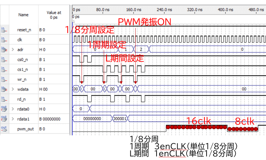
シミュレーション結果
TOP階層(pwm_top)でのシミュレーション結果です。狙った通りに動いていますね。
Verilogで書いてみる
まず分周回路から
VHDLコードをChatGPTでVerilog変換してみました。うまく変換できているようには見えます。
module en_gen (
    input wire clk,
    input wire reset_n,
    input wire adr,
    input wire cs_n,
    input wire wr_n,
    input wire rd_n,
    input wire [1:0] wdata,
    output reg [1:0] rdata,
    output reg clken
);

    reg [3:0] icnt;
    reg i4en, i8en, i16en;
    reg [1:0] isel;

    // Process for writing to isel
    always @(posedge clk or negedge reset_n) begin
        if (!reset_n) begin
            isel <= 2'b00;
        end else if (!cs_n && !wr_n && adr == 1'b0) begin
            isel <= wdata;
        end
    end

    // Process for reading from isel
    always @(posedge clk or negedge reset_n) begin
        if (!reset_n) begin
            rdata <= 2'b00;
        end else if (!cs_n && !rd_n && adr == 1'b0) begin
            rdata <= isel;
        end
    end

    // Process for counting in icnt
    always @(posedge clk or negedge reset_n) begin
        if (!reset_n) begin
            icnt <= 4'b0000;
        end else begin
            icnt <= icnt + 1'b1;
        end
    end

    // Process for generating i4en
    always @(*) begin
        if (icnt[1:0] == 2'b11) begin
            i4en = 1'b1;
        end else begin
            i4en = 1'b0;
        end
    end

    // Process for generating i8en
    always @(*) begin
        if (icnt[2:0] == 3'b111) begin
            i8en = 1'b1;
        end else begin
            i8en = 1'b0;
        end
    end

    // Process for generating i16en
    always @(*) begin
        if (icnt == 4'b1111) begin
            i16en = 1'b1;
        end else begin
            i16en = 1'b0;
        end
    end

    // Process for selecting clken based on isel
    always @(*) begin
        case (isel)
            2'b00: clken = i4en;
            2'b01: clken = i8en;
            2'b10: clken = i16en;
            default: clken = i4en;
        endcase
    end

endmodule
次にPWM発振回路です。
VHDLコードをChatGPTでVerilog変換してみました。うまく変換できているようには見えます。
module pwm_gen (
    input wire clk,
    input wire reset_n,
    input wire [1:0] adr,
    input wire cs_n,
    input wire wr_n,
    input wire rd_n,
    input wire [7:0] wdata,
    output reg [7:0] rdata,
    input wire en,
    output wire pwm_out
);

    reg [7:0] iperiod, iltime, ipcnt;
    reg iset, ipcmp, ipwm_out;

    // Process for writing to iperiod
    always @(posedge clk or negedge reset_n) begin
        if (!reset_n) begin
            iperiod <= 8'b00000000;
        end else if (!cs_n && !wr_n && adr == 2'b00) begin
            iperiod <= wdata;
        end
    end

    // Process for writing to iltime
    always @(posedge clk or negedge reset_n) begin
        if (!reset_n) begin
            iltime <= 8'b00000000;
        end else if (!cs_n && !wr_n && adr == 2'b01) begin
            iltime <= wdata;
        end
    end

    // Process for writing to iset
    always @(posedge clk or negedge reset_n) begin
        if (!reset_n) begin
            iset <= 1'b0;
        end else if (!cs_n && !wr_n && adr == 2'b10) begin
            iset <= wdata[0];
        end
    end

    // Process for reading from registers
    always @(posedge clk or negedge reset_n) begin
        if (!reset_n) begin
            rdata <= 8'b00000000;
        end else if (!cs_n && !rd_n) begin
            case (adr)
                2'b00: rdata <= iperiod;
                2'b01: rdata <= iltime;
                2'b10: rdata <= {7'b0000000, iset};
                default: rdata <= 8'b00000000;
            endcase
        end
    end

    // Process for counting in ipcnt
    always @(posedge clk or negedge reset_n) begin
        if (!reset_n) begin
            ipcnt <= 8'b00000001;
        end else if (en && (iset == 1'b0 || ipcmp == 1'b1)) begin
            ipcnt <= 8'b00000001;
        end else if (en) begin
            ipcnt <= ipcnt + 1'b1;
        end
    end

    // Process for comparing ipcnt and iperiod
    always @(*) begin
        if (ipcnt == iperiod) begin
            ipcmp = 1'b1;
        end else begin
            ipcmp = 1'b0;
        end
    end

    // Process for generating ipwm_out
    always @(*) begin
        if (ipcnt <= iltime) begin
            ipwm_out = 1'b0;
        end else begin
            ipwm_out = 1'b1;
        end
    end

    // Output pwm_out
    assign pwm_out = ipwm_out & iset;

endmodule
最後にTOP階層(分周回路+PWM発振回路)です。
VHDLコードをChatGPTでVerilog変換してみました。うまく変換できているようには見えます。
module pwm_top (
    input wire clk,
    input wire reset_n,
    input wire cs0_n,
    input wire cs1_n,
    input wire [1:0] adr,
    input wire wr_n,
    input wire rd_n,
    input wire [7:0] wdata,
    output wire [1:0] rdata0,
    output wire [7:0] rdata1,
    output wire pwm_out
);

    wire iclken;

    // en_genモジュールのインスタンス化
    en_gen u0 (
        .clk(clk),
        .reset_n(reset_n),
        .adr(adr[0]),
        .cs_n(cs0_n),
        .wr_n(wr_n),
        .rd_n(rd_n),
        .wdata(wdata[1:0]),
        .rdata(rdata0),
        .clken(iclken)
    );

    // pwm_genモジュールのインスタンス化
    pwm_gen u1 (
        .clk(clk),
        .reset_n(reset_n),
        .adr(adr),
        .cs_n(cs1_n),
        .wr_n(wr_n),
        .rd_n(rd_n),
        .wdata(wdata),
        .rdata(rdata1),
        .en(iclken),
        .pwm_out(pwm_out)
    );

endmodule
おわりに
今回は分周回路とPWM発振回路のコンビとする回路をご紹介いたしました。いずれもよく使用するシーンが多いのでどういうものかを理解していただければと思います。ありがとうございました。
この記事が気に入ったらサポートをしてみませんか?