[ロボ実験記録] Dobot magician + USBカメラでオブジェクトをホーミングする

これまで
dobot magicianを立ち上げたり、arucoマーカーで遊んでみました
今回
両者を組み合わせて、カメラ座標系とロボット座標系を統合してみます。
これにより、特定の物体を認識して、アームで移動するシステムの基盤が得られます
arucoマーカーのホーミング pic.twitter.com/kn8TNjHKYX
— 畠山 歓 Kan Hatakeyama (@kanhatakeyama) July 18, 2023
関連記事
USBカメラのキャリブレーション
今回のコード一式はこちら(一部ファイルは著作権の関係上、入れられないので、自分で調達する必要があります)
カメラの画像は微妙に歪んでいるので、それを補正する必要があります。
こちらの記事を参考にします。
まずは、適当にチェスボードの画像を用意します。
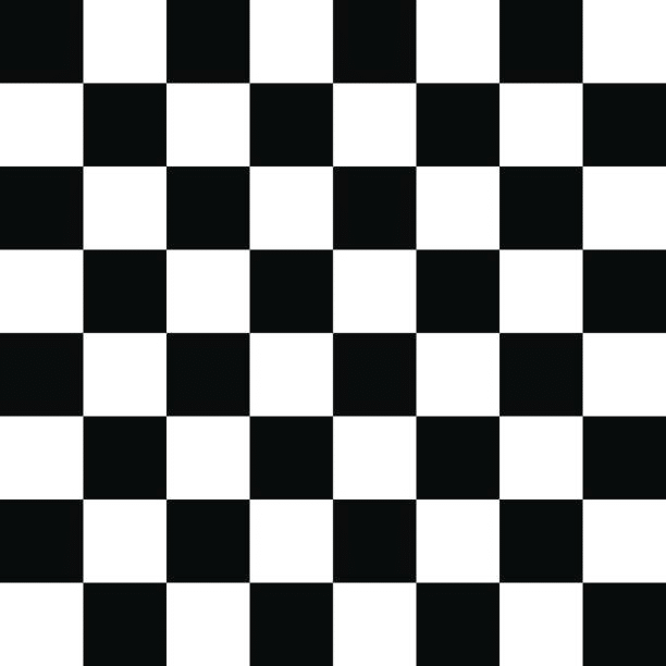
この画像を印刷 or ディスプレイに表示した状態で、以下のコードを走らせ、ひたすらチェスボードを撮影します
10回、チェスボードを認識できると、自動でループを抜け、datフォルダ内に保存する設定になっています(datフォルダを要作成)。
import numpy as np
import cv2
from IPython.display import clear_output
import matplotlib.pyplot as plt
import time
cap = cv2.VideoCapture(0)

if cap.isOpened() is False:
    raise("IO Error")

# termination criteria
criteria = (cv2.TERM_CRITERIA_EPS + cv2.TERM_CRITERIA_MAX_ITER, 30, 0.001)

# prepare object points, like (0,0,0), (1,0,0), (2,0,0) ....,(6,5,0)
objp = np.zeros((6*6,3), np.float32)
objp[:,:2] = np.mgrid[0:6,0:6].T.reshape(-1,2)

# Arrays to store object points and image points from all the images.
objpoints = [] # 3d point in real world space
imgpoints = [] # 2d points in image plane.

imgInd=0
detected_imgs=[]
while True:
    ret, img = cap.read()
    if ret == False:
        continue
    gray = cv2.cvtColor(img,cv2.COLOR_BGR2GRAY)

    cv2.putText(img,'Number of capture: '+str(imgInd),(30,20),cv2.FONT_HERSHEY_PLAIN, 1,(0,255,0))
    cv2.putText(img,'c: Capture the image',(30,40),cv2.FONT_HERSHEY_PLAIN, 1,(0,255,0))
    cv2.putText(img,'q: Finish capturing and calcurate the camera matrix and distortion',(30,60),cv2.FONT_HERSHEY_PLAIN, 1,(0,255,0))

    cv2.putText(img,str(imgInd),(30,80),cv2.FONT_HERSHEY_PLAIN, 1,(0,255,0))
    #cv2.imshow("Image", img)
    clear_output(wait=True)
    plt.imshow(img)
    plt.axis('off')
    plt.show()

    k = cv2.waitKey(1) & 0xFF
    # Find the chess board corners
    ret, corners = cv2.findChessboardCorners(gray, (6,6),None)
    # If found, add object points, image points (after refining them)
    if ret == True:
        print("detected")
        objpoints.append(objp)

        corners2 = cv2.cornerSubPix(gray,corners,(11,11),(-1,-1),criteria)
        imgpoints.append(corners2)

        # Draw and display the corners
        img_c = cv2.drawChessboardCorners(img, (6,6), corners2,ret)

        clear_output(wait=True)
        plt.imshow(img_c)
        detected_imgs.append(img_c)
        time.sleep(1)

        imgInd+=1

    if imgInd >= 10:
        break
    if k == ord('q'):
        break
撮影画像の確認(念のため)
for img in detected_imgs:
    clear_output(wait=True)
    plt.imshow(img)
    plt.axis('off')
    plt.show()
    time.sleep(1)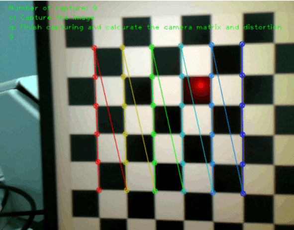
補正ファイルの保存
# Calc urate the camera matrix
ret, mtx, dist, rvecs, tvecs = cv2.calibrateCamera(objpoints, imgpoints, gray.shape[::-1],None,None)


np.save("dat/mtx.npy", mtx)
np.save("dat/dist.npy", dist)
cap.release()
cv2.destroyAllWindows()
オブジェクトのホーミング
Arucoマーカーの準備
以下の感じのコードで、Arucoマーカーを作ります
id=0のほか、適当にid=1,2,3で出力します
#arucoマーカーの生成
from cv2 import aruco
import matplotlib.pyplot as plt

dict_aruco=aruco.getPredefinedDictionary(aruco.DICT_4X4_50)
marker_id=0
size_mark=100
img=aruco.generateImageMarker(dict_aruco,marker_id,size_mark)
plt.axis('off')
plt.imshow(img,cmap='gray')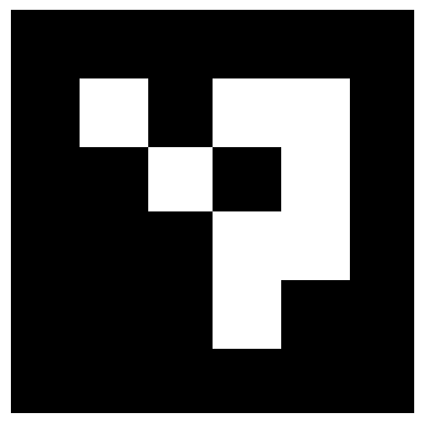
画像のサイズが2cm程度になるよう、印刷しました。
実際に印刷すると、1.8cmでした。このサイズは正確に測っておく必要があります。
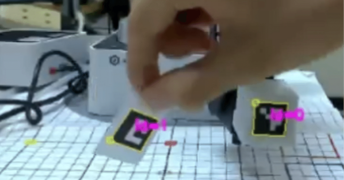
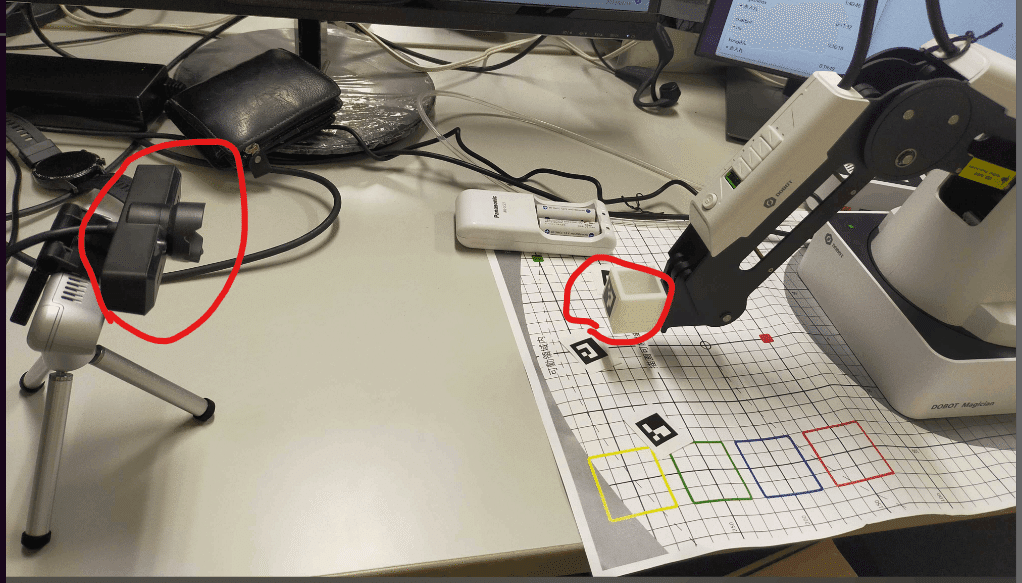
機材のセッティング
Dobotを配置し、その正面にUSBカメラをセットします。
Dobotのarmの先には、Aruco marker (id=0)を貼り付けておきます(写真には、3Dプリンタで自作したパーツがついていますが、特に必要ありません)。
Dobotの制御
関連するdll類を、公式サイトからダウンロードしてDobotDriverフォルダに入れる必要があります
初期化関連
from DobotDriver.DobotWrapper import DobotWrapper
dobot=DobotWrapper("COM3")
dobot.initiate()


from camera.USBCamera import USBCamera
from camera.ArucoDetect import ArucoDetect
import matplotlib.pyplot as plt
import cv2
import numpy as np
from IPython.display import clear_output

camera=USBCamera(0)

#マーカーのサイズ
marker_length=1.8/2

#補正ファイル
mtx=np.load('dat/mtx.npy')
dist=np.load('dat/dist.npy')
marker_lengthは、印刷したarucoマーカーのサイズです。
印刷物の辺の長さは1.8 cmだったんですが、なぜか2で割ると、正確な感じになったので、2で割っています。詳細不明
指定のaruco markerまでアームを動かす関数
def move_to_target_arco(target_id,dobot,ids,tvec,scale=9.9):
    #armの位置を取得
    arm_idx=np.where(ids==0)[0][0]
    arm_tvec=tvec[arm_idx][0]


    #targetの位置を取得
    target_idx=np.where(ids==target_id)[0][0]
    target_tvec=tvec[target_idx][0]

    #dobotの位置とtargetの位置の差分を計算
    diff_tvec=target_tvec-arm_tvec

    #x,y,zを軸を合わせる
    diff_tvec_dobot=np.array((
    -diff_tvec[2],
    diff_tvec[0],
    -diff_tvec[1],
    ))
    move_vec=diff_tvec_dobot*scale
    dobot_x, dobot_y, dobot_z ,_=dobot.get_position()

    #dobotの位置を移動
    to_z=dobot_z+move_vec[2]
    to_z=max(-100,to_z) #床への衝突を防ぐ
    dobot.move_arm(dobot_x+move_vec[0],dobot_y+move_vec[1],to_z,0)
後述する手法で、カメラ座標系におけるマーカーの位置をtvecとして取得できます。 移動すべき距離は、 (指定のarucoマーカー座標) - (アームにつけたarucoマーカー座標)です。 これをdobotの座標系に変換しています。
あとはループを回すだけです
import time
target_id=1

dobot.move_arm(200,0,0,0)  #アーム位置を初期化

while True:
    frame=camera.get_frame()
    aruco_detector=ArucoDetect()
    corners,ids=aruco_detector.detect(frame)
    rvec, tvec, _ = cv2.aruco.estimatePoseSingleMarkers(corners, marker_length, mtx, dist)

    if len(corners)>0:
        try:
            cv2.aruco.drawDetectedMarkers(frame, corners, ids, (0,255,255))
            cv2.drawFrameAxes(frame, mtx, dist, rvec, tvec, marker_length/2)
        except:
            pass

    try:
        move_to_target_arco(target_id,dobot,ids,tvec)
    except:
        pass
    clear_output(wait=True)
    rgb_frame = cv2.cvtColor(frame, cv2.COLOR_BGR2RGB)
    plt.imshow(rgb_frame)
    plt.axis('off')
    plt.show()
    time.sleep(0.1)

    #print(tvec)
estimatePoseSingleMarkers
aruco markerの座標を取得します。rvecは回転ベクトル、tvecはカメラからの並進ベクトルです
drawDetectedMarkers, drawFrameAxes
取得したベクトル類の描画です
move_to_target_arco
先述の通り、アームを移動する処理になります
その他
描画などの処理です
カメラ目線ではこんな感じです
カメラ目線 https://t.co/hjvW4dLAcx pic.twitter.com/H05uksW3Ok
— 畠山 歓 Kan Hatakeyama (@kanhatakeyama) July 18, 2023
今後
arucoマーカー以外の物体検出を、深度カメラ&deep learningで行いたいです
この記事が気に入ったらサポートをしてみませんか?