DELTA ANCHOR #3 Final

Hi, everyone! How are you?
I’ll announce the “DELTA ANCHOR #3 Final episode”.
I also rewrote the first and second episodes, which had been stagnant for a long time. I rewrote the Main plate, Skid plates, and the BATMAN etc. Please see episodes 1 and 2, too.
Let’s get started🪛
皆さんこんにちは〜
デルタアンカー第3話、最終回です。
そしてずっと停滞していたデルタアンカー第1話と第2話を書き直しました。メインプレートやローラー周辺、バットマンなど色々書き直されていますのでそちらも是非。それでは始めます💁♂️
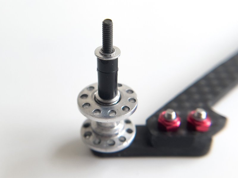
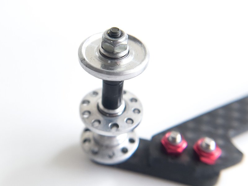
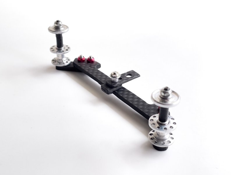
6.Main plate assembly

In the case the large tires, Fine adjust the height of the Main plate with large washers.
お好みでメインプレートの高さを微調整。


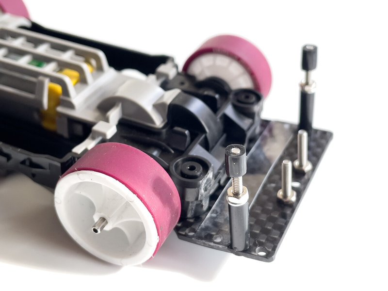
Finished ✔️
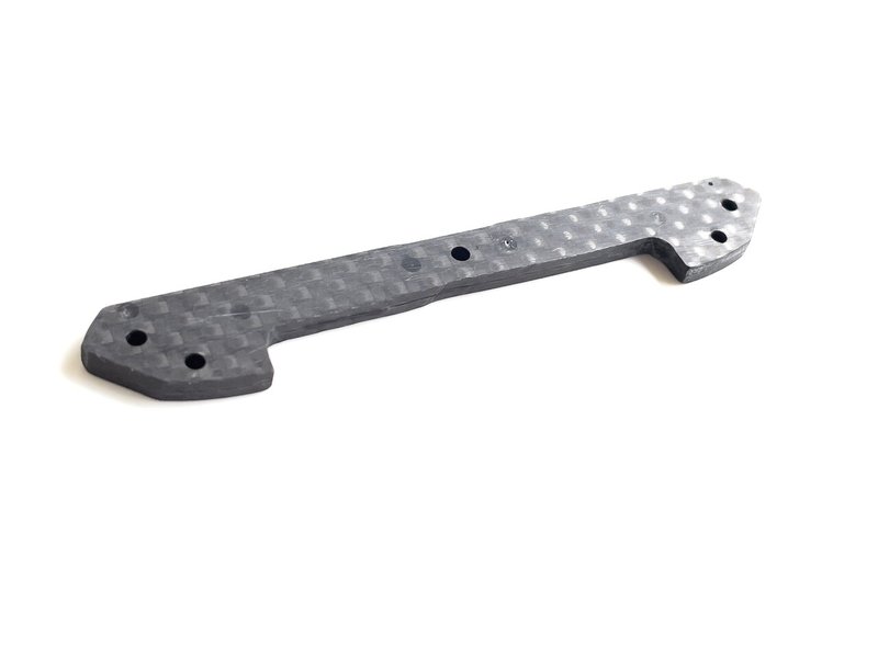
7. Center plates
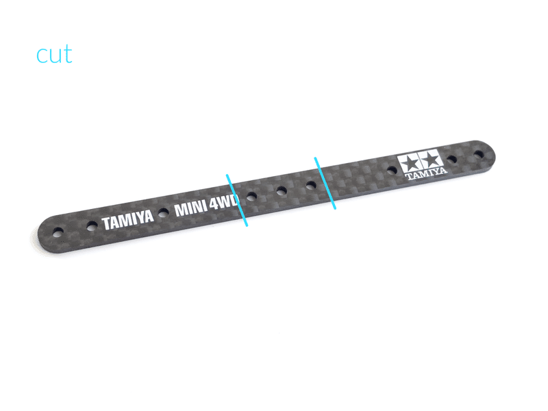
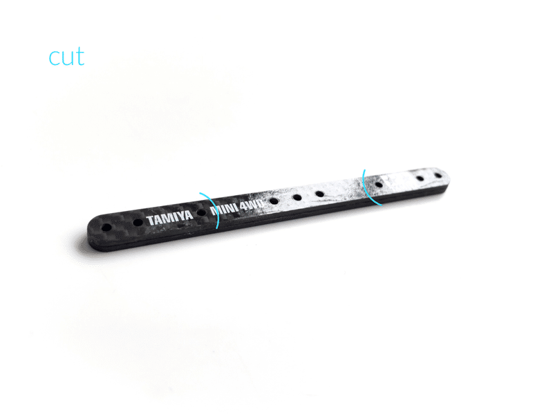
[57-Link bar]
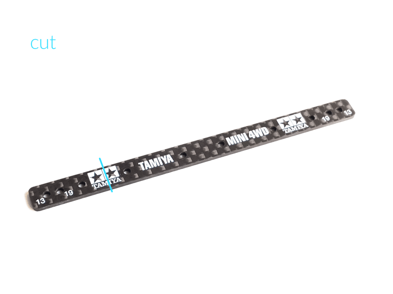

5.7mm from hole edge to bar end
穴端からバーエンドまで5.7mm
Points
If the length here is short, the screws on both sides will bend easily
ここの長さが短いと両隣のビスが曲がりやすいです。まぁ曲がる時は曲がるのですけどね笑。


Finished ✔️


When the main plate was extended by shifting it by one hole, the screw at the tip did not bend. For your reference...
メインプレートを1穴ずらして前側に延長すると先端のビスが曲がらなくなりました。ご参考まで。
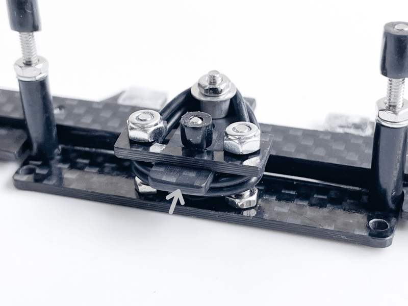
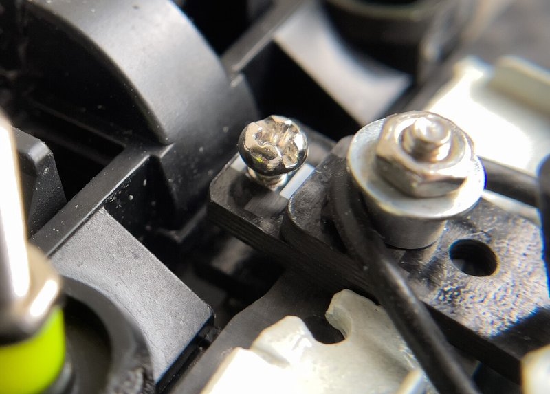
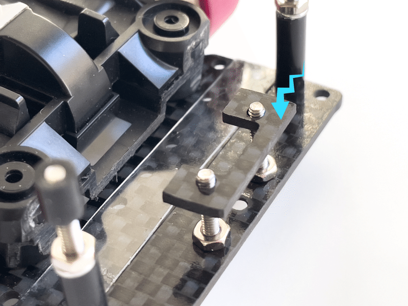
[Limiter plate / リミッター]


Temporary assembly
仮組み


Adjust by changing the thickness
厚みを変えて調整

Press lightly
軽く押す

It hits here when you push the Top Rollers
スタビローラーを押すとここに当たるように


It will be adjusted after assembling all the parts, but as shown in the photo, adjust the thickness so that it hits only when the Top rollers are lightly pressed. It’s normal that there is a slight gap in the neutral position. (Adjusted so that it doesn’t hit in the neutral position)
If you assemble it like the tutorial, it's probably too thick, please file the carbon.
On the other hand, if the Top rollers are pressed lightly and the angle becomes negative, it means that the thickness is insufficient. Fine-tune this gap.
全ての部品を組み立てた後の調整になりますが、写真のようにスタビローラーを軽く押した時だけ当たるように厚みを調整します。ニュートラル位置でほんの少し隙間があるのが正常です。(ニュートラル位置で当たらない位に調整)
こちらのチュートリアルのように組み立てるとココが厚すぎる場合があります。このカーボンを少しずつヤスリましょう。
一方、スタビローラーを軽く押した時にアッパースラストになる場合は厚みが不足してることを意味します。高速LCでコースアウトする原因になります。同じくこの隙間を微調整します。
Gap adjustment method
File carbon, or apply super glue or polycarbonate
カーボンをやすりで薄くしたり、瞬間接着剤を塗り重ねたりポリカを貼って厚みを調整
About Limiter plate
It has the role of preventing negative angles when the top rollers are pressed. Effective for lane changes and jump landings. If this adjustment is successful, you’ll be able to pass through the lane change with fewer roller angles.
スタビローラーに過入力があった時にアッパースラストを防ぐ役目があります。名前が示すようにリミッターですね。LCやジャンプ着地に効果的です。この調整が上手くゆけば、より少ないスラスト角でLCをクリアできると思います。
[Adjustment screw type]
[調整式リミッター]

You can make a 1.9mm hole in the limiter and attach the adjustment screw. It may be convenient because you can fine-tune the clearance by turning the screw.
In this case, I think it's a good idea to glue carbon scraps to the chassis side to make a plate that an adjust screw will hit.
リミッターに1.9mmの穴を開けて調整ビスを取り付けるのも良いですね。ネジを回してクリアランスを微調整できるのでラクかもしれません。この場合はシャーシ側にカーボン端材を接着してビスが当たる板を作っておくと良さそうです。
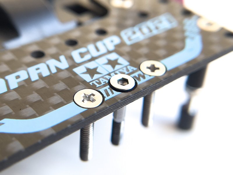
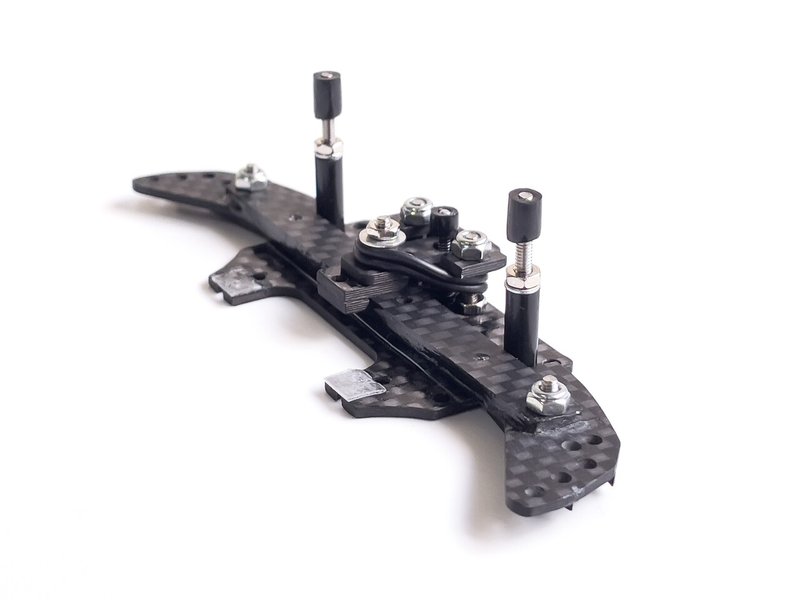
8. Bumper assembly

M2x12, Limiter plate, 57-Link plate, 3mm Aluminum spacer, Large washer, and Small nut
M2x12, リミッター、57リンク、3mmスペーサー、大ワッシャー、小ナット

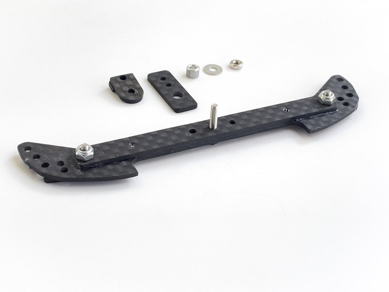


Insert a large washer between the limiter and the 57 link plate.
リミッターと57リンクの間に大ワッシャーを入れてください。

Place the 57 link plate after the large washer.
大ワッシャーの次に57リンクを置きます。


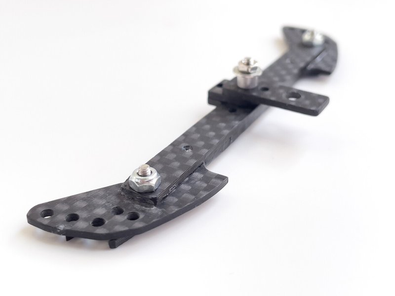
Finished ✔️
9. Adjust plate
It's a little difficult to make. Practice a few times and get the hang of it.
ちょっと作るのが難しいです。数回練習してコツを掴みましょう。
Please Use carbon
カーボンを使用


Temporary assembly. It doesn't move smoothly.
仮組み。スムーズに動かないと思います。


Spread a little sideways. a little🤏
少し横に広げます。ほんの少し。
Points
Please don’t spread back and forth
前後に広げてはいけません

The Adjust plate now moves smoothly.
引っ掛かりなく動くようになりました。


Finish to 2.2 mm
2.2mmに仕上げます

Need a gap
隙間が必要です

You can adjust the hardness of the vertical stroke. If it’s uncut, the vertical stroke is quite stiff, please cut it a little. The shorter it’s, the softer it becomes. However, if it’s short, LC may be difficult.
縦ストロークの強弱を調整できます。未加工だと上下動が固いのでカットして調整しましょう。短かいほど上下動が柔らかくなります。ただし短いとLCがちょっと難しいかもしれません。
10. 13-Shaft and 50-Spring
[13-Shaft]

25mm Cap screw


Finished ✔️
[Rubber tube]

t = 3mm
[50-Black spring]


5.0 rolls
5.0巻
11. Assemble


This 50 spring is often lost during maintenance, it's a good idea to glue them to the main plate side with Super Glue.
50黒バネはメンテナンス中に紛失することが多いので、瞬着でメインプレート側に接着しておくと良いかもしれません。


19mm


Finished ✔️
points
There are two O-rings in the photo, but three may be better. In the case of the Three O rings, the Lane change becomes easier and the air turn is decided. Also, I think that the passing speed of the wave section will be faster.
写真のOリングは2本ですが、3本の方が良いかもしれません。LCがラクになり、エアターンが良く決まります。ウェーブ抜けも速いかと思います。
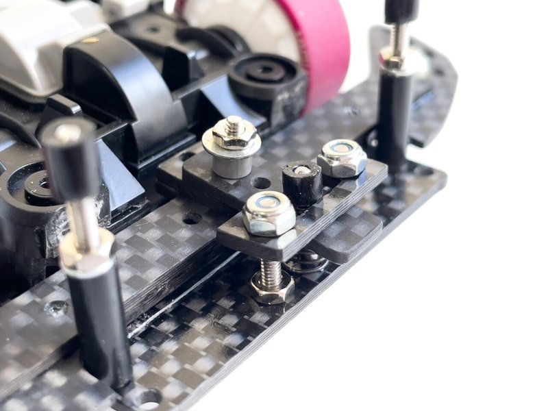
12. Adjustment / 調整
[Limiter plate]

This gap is not good.
この隙間を無くしましょう


As I explained a little in item 7, I think that there is a gap between the main plate and BATMAN in the assembled neutral state for the time being. If the limiter is too thick, a gap will be created, adjust the thickness of the limiter with a file that this gap disappears. Adjust the limiter thickness that the bumper ends doesn’t rattle up and down.
To adjust the thickness of the limiter, adjust it to the roller angle of your choice and then find the best thickness.
項目7でも少しご説明したようにリミッターの厚みを調整します。とりあえず組み立てられたニュートラル状態ではメインプレートとバットマンの間に隙間があるかもしれません。リミッターが厚い場合があり、バットマンとメインプレート間に隙間ができるので、この隙間が無くなるようにリミッターの厚みを瞬着やヤスリで調整し、バンパー端(ローラー)が上下にカタカタ動かないように調整します。
リミッター厚の調整は大体のお好みのスラスト角度に合わせてからベストな厚みを探してください。
Points
1) Adjust the limiter thickness so that the bumper end does not rattle up and down with your favorite roller angle.
2) Adjust that it doesn’t become a negative angle when the stabilizer is lightly pressed.
3) If the bumper doesn’t move up and down in the neutral position, and the roller angle doesn’t become a negative angle by lightly pressing the stabilizer, it is OK even if there is no gap in the limiter.
1) お好みのスラスト角でバンパー両端が上下にカタカタ動かないようにリミッター厚を調整
2) スタビ軽押しでアッパーにならないようにリミッター厚を調整
3) ニュートラル位置でバンパーが上下にカタカタ動かず、スタビ軽押しでスラスト角がアッパーにならない場合はリミッターに隙間がなくてもOK
[Main plate angle]


In Delta Anchor Episode 1, I introduced how to glue polycarbonate to the Main plate. However, in the case of MS chassis, it was overwhelmingly easier to file the bottom of the unit diagonally.
デルタアンカー第1話でメインプレートにポリカを接着して角度付けする方法をご紹介しましたが、MSシャーシの場合はユニット底面を斜めにヤスる方が圧倒的に簡単でした。これはバクスラアンカーと同じです。
Points
File to about negative 3 degrees
約マイナス3度に削る
[Bumper angle]

スラスト調整ナット
バクスラと違いスラストはしっかり入れてください。問題なくLCをパスできるようなら少しずつ抜くような使い方がオススメ。
[Vertical stroke hardness]

You can adjust the hardness of the vertical stroke.
上下動の固さを調整できます。
[Brake area]

Paste thick polycarbonate
厚めのポリカを貼ります
[Damper grease]

Apply damper grease if necessary. You should apply a generous amount just behind the plastic spacer. However, it can be used without applying grease. it's to your liking.
必要ならダンパーグリスを塗ってください。プラスペーサーのすぐ後ろにたっぷりと塗ると良いですよ。ですが塗らなくても問題なく使用できます。お好みで。
[Lantern screws]

Bend the screws slightly with pliers that the lantern moves smoothly. A little🤏
そのままでは提灯がスムーズに動きません。ラジペンで少しビスを曲げてください。少しです。
[13mm Main Rollers]

This is the standard setting of the delta anchor. The most important point is to install the 13-12mm Double aluminum rollers low. Please adjust the height of Double Aluminum Rollers referring to the photo.
However, if you lower the front roller too much, you may not be able to pass through the LC. In that case, try raising it a little.
Please try various things!
写真は推奨セッティングです。気軽に試してみてください。こちらのポイントは13-12mmダブルアルミローラーを低く装着すること。写真を参考にローラーの高さを調整してみてください。
ただし、フロントローラーを下げすぎるとがLC入らない場合があります。その時は少しずつ上げてみてください。
色々遊んでみてくださいね!
Points
The 12mm roller should be below the front axle.
12mmローラーは車軸より下にある必要があります

As you continue reading this tutorial, God Washers-2 will appear. You can easily install the roller in a low position, so please give it a try✨
記事を読み進めると、14項のエクストラエディションで神ワッシャー2が登場します。簡単にローラーを低く取り付けることができるので是非お試しください。
[Top Rollers]

Next is the Top Rollers. Use the 30mm cap screws to mount the 13mm Aluminum Rollers in high positions. Use worn 13mm Aluminum Rollers. I recommend the one with a slightly smaller outer diameter.
次はスタビローラー。30mmキャップスクリューを使い、13mmアルミローラーを高い位置に取り付けます。こちらの13mmアルミローラーは摩耗して外径が少し小さくなったものがオススメ。
Points
Use a slightly 12.5mm smaller roller for the 13mm Top roller and install it in a high position.
13mmスタビローラーは少し小さな12.5mmローラーを使用し、高い位置に取り付ける
If you are using a new 13mm Aluminum Rollers, try running a mini circle course on your work machine and make a slightly smaller 13mm rollers. For the time being, about 12.5mm is good.
もし新品の13mmアルミローラーをお使いの場合は、ワークマシンでミニコースを走らせるなどして少し小さめの13mmローラーを作ってみてください。とりあえず12.5mm位がいいですね。
There are various methods to change the outer diameter of the 13mm rollers. Please guess🙏
If it is difficult to procure a 12.5mm diameter stabilizer, it is a good idea to use the 830 for the stabilizer.
もし12.5mm径スタビの調達が難しい場合は、スタビに830を使うのもオススメ。
Points
If it’s Top 13mm and Main 13mm, the corner is slow😅
スタビ13mm、メイン13mmだとちょっとカーブ遅いですね。
[Tube stabilizers]

In Japan it’s called “Yunomi”🍵
That setting was impressive! It has fast cornering and is good at changing lanes.
The roller screw in the photo is 30 mm, but a 25 mm cap screw is also acceptable.
↑こちらもGood。LCに強く、貼り付くようにクリアします。スラスト角を増やしてもコーナー減速が少ないのも特徴。
写真のローラーネジは30mmですが、25mmキャップスクリューでもOKです。
Points
The gear stabilizer that uses a the crown gears are also recommended.
LCクリア率は湯のみほどではありませんが、片軸のクラウンギアを使ったギヤスタビも悪くないです。カーボンクラウン等でどうぞ。ギアスタビは緩みやすいのでナット止め推奨。
[Slide stroke hardness]
The tension of the O-ring changes as you move the holes in the main plate closer or further apart, allowing you to adjust the overall stroke hardness.
メインプレートの穴位置を寄せたり離すとOリングのテンションが変化し、全体的なストロークの固さを調整できます。

Normally, fix it with a nut while pulling the jig close to the main plate, and make a 2 mm hole.
通常はメインプレートとジグを寄せながらナットで固定して2mm穴を開けます。(デルタアンカー#1参照)

If you want to make the stroke feel harder, try tightening the nut while separating the jig from the main plate to make a 2mm hole.
もし全体的なストローク感を固くする場合は、ジグとメインプレートを遠ざけながらナットを締めて2mm穴を開けてみてください。硬さ感は結構変わります。
[fine-tune the cut line]

You can adjust the backslide stroke by changing the cut line. The amount of backslide of the roller is recommended to be about 1.5mm to 2mm.
カットラインを変更するとバックスライド量を調整できます。ローラーのバックスライド量は1.5mm〜2mm位がおすすめ。デルタアンカーの場合はバクスラアンカーよりも少なめが◎
Points
The video at the beginning has a lot of strokes.
冒頭の動画はかなりストローク多いです🙏
13. Detail


It's a good idea to apply Tamiya tape to prevent injury.
怪我しないようにタミテ貼ると良いですね。


Completed ✔️
14. Extra edition

It’s a modification for advanced users. Furthermore, the roller can be installed lower. Bumper rigidity is high. The roller screw uses a 25 to 30mm countersunk cap. Please make the countersunk cap roller screw separately. The bumper position is too low and will interfere with the brakes. A little ingenuity is required. 9mm rollers can also be used. Since the bumper rigidity is high, it is easy to get caught when landing. The bumper shape is the best, so you can make amazing corner dives.
番外編。ちょっと上級者向きなエクストラエディションです。さらにローラーを低く装着できます。バンパー剛性が高いです。ローラービスは25〜30mm皿キャップを使用。皿キャップローラービスは別途ご作成ください。バンパー位置が低くブレーキと干渉するため少し工夫が必要です。13mmローラー設計です。コーナーダイブに特化したバンパー形状です。
Test machine specs
・We used the MS chassis
・Suspension / B-flexible type1 and type2 prototype
・Front gimmick / Delta anchor extra edition
・Rear gimmick / 2STEP EVO 11mm roller holes
・Front roller width / 103.5 mm
・Rear roller width / 104.5 mm
・Front and Rear roller length / 128 mm
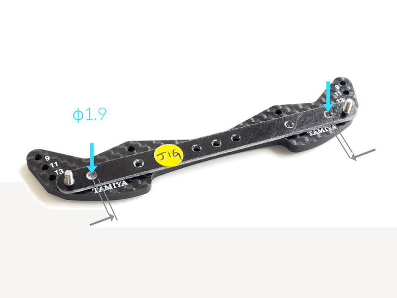
[Make the Bumper]

Two plates glued
接着します。


Actually, it’s difficult to make the accurate holes because the jig holes are large, so lightly close the blue hole of the FRP bar with super glue and re-drill it with 1.9mm. Make an accurate jig.
実はこのジグ穴が結構大きくて正確な穴を開けてゆくのが難しいため、写真のFRPバーの青穴を瞬着で軽く塞ぎ、1.9mmドリルで穴を開け直します。正確なジグを作りましょう。


標準タイプジグ

標準タイプジグのローラー位置
Make the 1.9mm holes at the position shown in the photo. When using the 13mm rollers, the roller comes very close to the front tires. This jig hole position is standard type.
写真の位置に1.9mm穴を開けます。例えば13mmローラーを使用した場合、フロントローラー位置はフロントタイヤにかなり接近します。こちらのジグの穴位置を標準タイプとします。
オフセットタイプジグ

ジグ穴位置を内側に寄せた場合
If the jig hole position is offset (inset??) inward, the front and rear roller distance will be longer. In other words, the 13mm front rollers will move far away from the front tires. Please try to make a jig with the hole position processed to your liking. (For example, try offsetting the jig hole 1.5mm inward on one side, Rollers move away from tires about 5mm.)
もしジグの穴位置を内側にオフセットした場合は前後のローラーベースが長くなります。つまり13mmフロントローラーはフロントタイヤから前方に遠ざかります。お好みに合わせて穴位置を加工したジグを作ってみてください。(例えばジグ穴を片側1.5mmずつ内側にオフセットしてみてください。前ローラーは約5mmタイヤから遠くに離れます)


カットライン

カットラインを微調整
↑ You can adjust the backslide amount by changing the cut line. As the amount of backslide increases, it tends to be difficult to change lanes. Even a small amount of slide will do a good job, so as a guide, adjust the roller that it slides back 1.5mm to 2.0mm. As for the adjustment method, add super glue to the bumper or scrape it to adjust the gap.
The video at the beginning of the article has a feeling that there are too many strokes. For your reference.
こちらのカットラインを変更するとバックスライド量を調整できます。バックスライド量が増えるとレーンチェンジが難しくなる傾向があります。目安はローラーが1.5mm〜2.0mm程度バックスライドするように隙間調整してください。調整方法はカットラインを変更したり、バンパーに瞬着を盛ったり削ったり…
Points
The video at the beginning has a lot of strokes.
冒頭のデモ動画はかなりストローク多いです。あれはやりすぎです笑


Backside


接着時に微妙にズレるとローラーの座りが悪くなり、ローラーが傾いてしまい不調の原因に。ド真っ直ぐに接着してください。


Adjusted to 103.5 mm
103.5mmに調整
Points
Please decide the front width. 103.5mm is an example. Is your choice. 103.5mm is my favorite positions.
フロントローラー幅は自由に決めてください。103.5mmは一例ですが、とりあえず103.5mmにしておけば間違いないと思います。

After deciding the roller width, drill
ローラー幅を決めてドリル


瞬着で塞ぎます

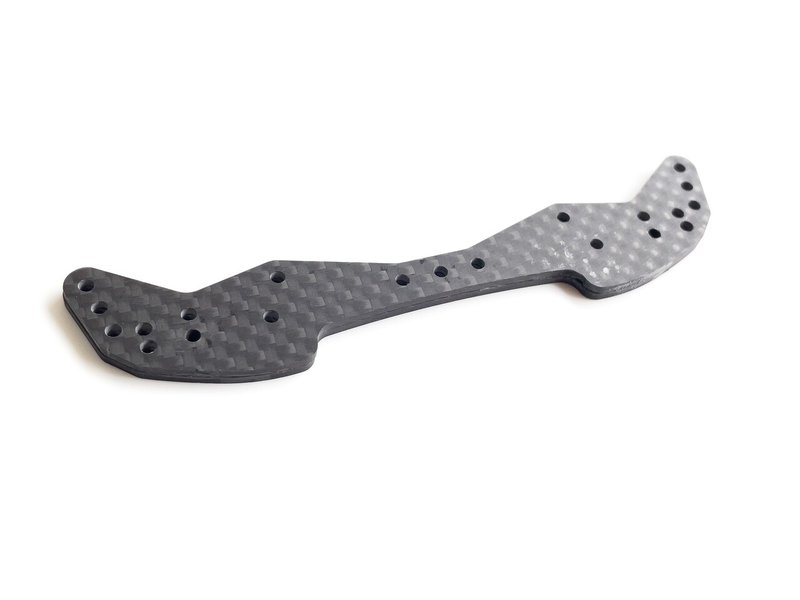
These are Master plate and Child plates
親板と子板

Please glue these.
親板と子板を接着します。
Points
Check the roller width again and glue them together. If these are not glued, the roller width will change during running.
再度ローラー幅をチェックし接着してください。これらを接着しないと走行中にローラー幅が変化し不調の原因に。

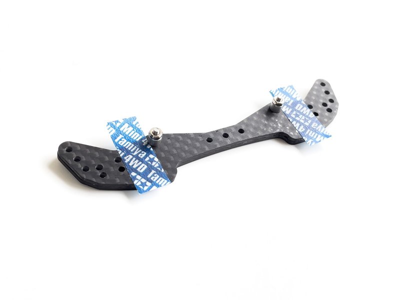
These are strong glues made in Japan
接着は遅乾性のメタルロックがおすすめ。位置決めできてガッチガチです。一度ビスを外して接合面にメタルロックを塗って接着してください。そしてローラー幅をチェック&位置決めしてから再度ナットを本締めし、約一時間ほど放置します。
Points
Use the super glue
3GでもOKOK!


Back side edge chamfer
裏角面取り


The bumper edges hits the slope before the sponge brake. That is, the brakes don’t work. Cut that the bumper edge doesn’t hit the slope.
スポンジブレーキより先にバンパーエッジがスロープにヒットします。つまりブレーキが仕事しません。バンパーエッジがスロープに当たらないようにカットしてください。
[Three-plates type]

Rough drawing😅
なんかすみません💦
If you use 3 plates, you can lower the roller a little more.
子板を3ピースにすればもう少しローラーを下げることが出来ますよ。


glue
3Gでも良いです。お好みで。

Frontside / 表側

Backslide / 裏側


Positioning and gluing.
位置決めと接着。

Scraping carbon and screws.
ネジごと削るスタイル。ブレーキと干渉しませんように。

いいですね!
nice!

Three plates type Finished ✔️
3プレートタイプ完成!
[Main plate]


Extending the main plate will help solve the brake interference problem.
メインプレートを延長しておくとバンパーとブレーキの干渉問題を解決するのに役立ちます。

Stick two pieces of polycarbonate
ポリカを2枚重ね貼り
[the Rollers install]

30mm cap screws modified
Since the child plate is made of two carbon sheets, you can use the countersunk cap screw, but if you have one carbon plate, you cannot use the countersunk cap.
子板はカーボン2枚なので皿キャップスクリューを使うことができますが、もしカーボン1枚なら皿キャップはNGです。


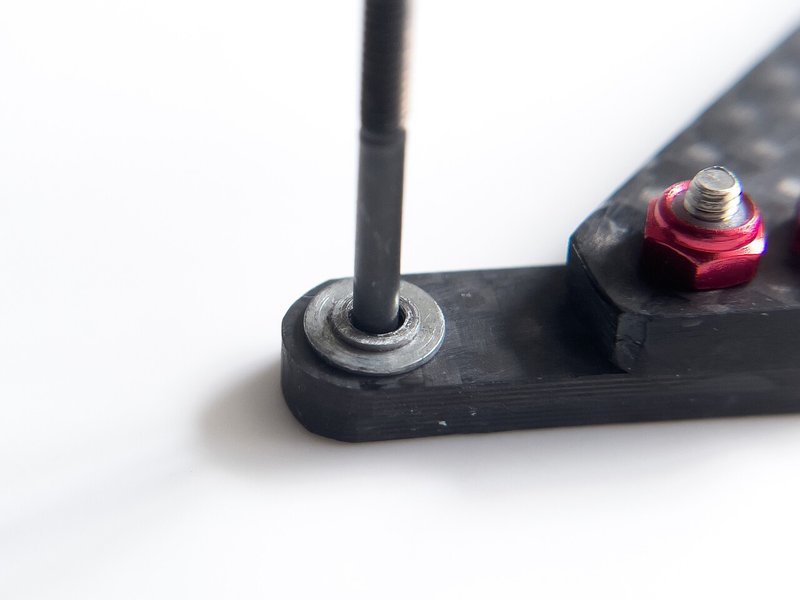
About GOD washer
Tested the god washer. The rear rollers is good, but the front rollers is out of order in half a day. Please use a normal bearing washer for the time being. I will add it when I have an idea.
神ワッシャー
ベアリングワッシャーの代替品。小ワッシャーを加工したものです。ローラー位置を下げるのが目的でした。
リアローラーは大丈夫でしたが、フロントは半日持ちませんでした。COするとローラーが傾いてしまって使えません笑。普通のタミヤ純正ベアリングワッシャーを使ってください。何かアイデアが浮かんだら追記します。

It’s a counterbore. If you have a machine tool, try counterbore.
バンパーザグってみました。もし工作機械をお持ちならザグると良いかもですね。


Finished ✔️
Chamfer sharp edges.
シャープエッジは面取りしましょう。
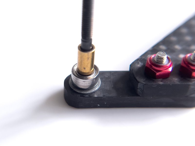
[God washers-2 / 524 RACING type]

These are God washers-2. The front is after processing
神ワッシャー2。手前が加工品。
Introducing God Washer 2, which can lower the roller position without counterbore the roller hole!⁵²⁴𝙍𝘼𝘾𝙄𝙉𝙂's idea.
Use a flat water grindstone or a plate file to thinly scrape the genuine bearing washer. It's difficult to scrape straight, but you'll soon get used to it. The bearing washer can be scraped by minus 0.3 mm, and the large washer can be omitted, so the roller position can be lowered by minus 0.4 mm, 0.7 mm in total. This can also be used for 2STEP EVO.
バンパーをザグらなくてもローラー位置を下げることができる神ワッシャー2が登場!⁵²⁴𝙍𝘼𝘾𝙄𝙉𝙂 さんのアイデアです。
平砥石(包丁研ぎ)や板ヤスリを使って純正ベアリングワッシャーを削ります。ちょっとコツがあるけどすぐに慣れます。ベアリングワッシャーを削りマイナス0.3mm、大ワッシャーを省略することができるので更にマイナス0.4mm、合計約0.7mmローラー位置を低くすることができます。こちらは2STEP EVOにも使えます。是非是非!

Prepare to new bearing washers. The God washer is basically used on the underside of the rollers. (The bearing washer on the upper side of the rollers are OK without processing)
新品のベアリングワッシャーを用意します。基本的に神ワッシャーはローラーの下側に装着します。(ローラー上側のベアリングワッシャーは無加工でOK)

Make the 3.2mm holes in a FRP scrap.
FRP端材に3.2mm穴を開けます。

Install a bearing washer in the 3.2mm hole. There are good clicking sounds.
3.2mm穴にベアリングワッシャーを嵌め込みます。パチンと音がします。気持ちいい!

Scrape with water
板ヤスリで水研ぎ。
Points
The thickness should be evenly reduced. Let's file by rotating up / down / left / right, clockwise / counterclockwise.
厚みを均等に薄くする必要があります。左右・上下・右回転・左回転などで削ってみてください。
上上下下左右左右BA!

scrape evenly?
均等に削れてますか?

Finished ✔️
Points
Inadvertently scraping diagonally will create an extra roller angle. Check if the rollers are tilted.
うっかり斜めに削ると不用なスラスト角が生じます。均等に水平にヤスリましょう。最後にローラーが傾いていないか組み立てチェックしてください。
[Re assembling]

Re assemble. Peripheral parts can be used as they are.
という訳で組み立て再開。周辺部品はそのまま使えます。

Finished ✔️
[Detail of Extra edition]


The Main plate is stretched forward.
メインプレートが延長されています。

Try cutting the main plate front end edge round that the main plate doesn’t get caught in the jump landing.
ジャンプ着地の時にメインプレート前角が引っ掛かるのを防ぐために前角をカットすると良いですね。


Completed ✔️
15. Special thanks 🇯🇵🇮🇹
TOY’s CAP boss
⁵²⁴𝙍𝘼𝘾𝙄𝙉𝙂
i_ale_
ZERO GARAGE
🅾️gℹ️
tech21v
And a lot of everyone🙏✨
Thank you so much!
16. Afterword
The Delta Anchor project, which started in the summer, has been completed this fall. It was really long ...😵💫
Various variants (techniques and methods) will appear in this work, but please choose your favorite method and create a unique delta anchor. I hope it will help you with a fantastic corner dive.
I wish you a greater success in every situations! See you!
今夏に始まったデルタアンカープロジェクトが今冬完結しました。いやぁ本当に長かった…。私の不手際で記事更新日時が9月24日になっていますが、正しくは2021年12月3日です。
「故障が少なく調子が変わらず調整カンタン」が不変的なギミックコンセプトですが、一言でまとめると「バンパー低いとアンダーローラー省略できで最高よねー」みたいな作品でしたね笑
本作中には色んなバリエーションが登場しますが、お好きな方法を選択してあなただけのデルタアンカーを作ってみてください。華麗なコーナーダイブが実現することを願っています。
全てにおいて良い結果になりますように。。
ではまたね!
-.-.-.-.-.-.-.-.-.-.-.-.-.-.-.-.-.-.-.-.-.-.-.-.
↓EVOも是非是非!
Please feel free to follow me🤍フォローも何卒!
instagram.com/beck.jpn/
twitter.com/beckjpn_/
note
note.com/beck_jp/
YouTube
youtube.com/c/BECKJPN
(c) 2021 BECKJPN All Lights Reserved
この記事が気に入ったらサポートをしてみませんか?