忘れちゃうTOP達 [TouchDesigner]

随時更新されます
TouchDesigner UI
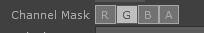
TOP等にあるグレー/白のボタンのUIは
グレーがON、白がOFFを表している。
Select
TOPのSelectは任意のパスを入れることで入れ子構造になっていて遠いTOP OPも取り出すことができる。

Cache
Cache Sizeで保存する枚数
step Sizeで何枚置きに保存するか。キャッシュの取得割合を決めます。
output indexでどこスタートで保存するか
0なら最新、負なら過去のフレームスタートで遡っていく
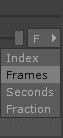
単位は右側で変更できる。

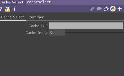
Cache select
Cache TOPを選択して、
index でCacheを選べる
Cacheは0からスタートで負の方向へ進む。
一枚目のキャッシュが0、二枚目が-1
Cache枚数はChcheTopのCache Sizeに依存する
Cache Size3の時に、Cache Select TOPのCache indexを-50や-20とかにしても結果は最後のCacheが返ってくるだけ(今回で言えば3枚目)
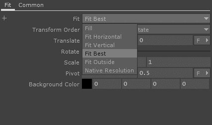
Fit
inputのアス比を崩さずにFitのCommon pageのOutput Resolutionを指定してあげることでその解像度にFitすることができる。
Fitの項目でどういう風にFitするかを選べる。Fit Bestでは解像度比率によって、Fit Horizontal か Verticalかが選ばれる。
Native Resolutionを選ぶと、input側のresolutionがデカい場合は、実際にfit側のresolution分しか使わないように表示し、input側のresolutionが小さい場合は、小さく表示される。
Displace
input0がsource video
input1がdisplace map
displace mapに指定した画像の
座標と重なる部分が影響を受ける
そして、その明るさが明るいほど、
影響を受けまくる
Source Midpoint
どこへ移動させるかを座標で指定する
0.0に指定すれば、左下めがけて移動していく
Displace weight
どのくらい変化させるかの重み
source midpointの方向へ移動していく
Offset
予めの座標の位置を変更するオフセット
Offse Weightでその重みも変更できる


Limit
TOPのRGBの値を制限を掛けたり、
TOPのcolor / positionをQuantizeできたりする。
LimitタブではMax / Minを超える値をその値でClampしたり、
Loopしたり、ZigZagにしたりできる
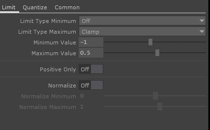


Quantize Value
Ceiling / Floor / Roundを選べる
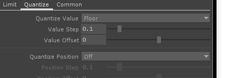

Quantize Position 縦横両方で
Ceiling / Floor / Roundを選べる
モザイク的にNearest的な感じになる。

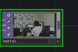
Matte
マット画像を基に合成する
input 3がマット画像
input1 / 2が以下のルールで合成される
Matte TOPは、input3のアルファチャネルをマットとして使用して、input1とinput2を合成します。 input3のアルファチャネルの白(1)ピクセルはinput2の上にinput1を描画し、黒(または0)はinput1を透明にし、そのピクセルにinput2画像を残します。
[引用] http://ted-kanakubo.com/touchdesigner-jp/?p=211

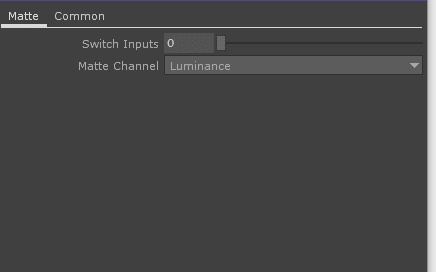
input3の何を参照するのかは、 Matte channnelで設定できる。
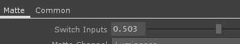
switch inputsでinput1と2をの重ね合わせるイメージを変更できる。
inputを単純に繋ぎ変える効果を得られたり、途中の感じも得られる。
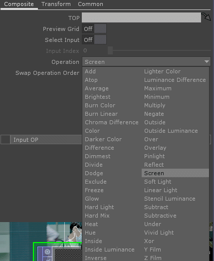
Composite
photoshop等でもおなじみのブレンドモード的な合成を行える。
Add TopやScreen TOP , over TOP, Multiply TOPなどはinputを[0][1]の二つしか持てないが、Composite TOPではinputを複数持てるのが特徴。
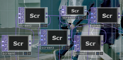
inputを複数持てるから便利なのだが、変なバグが存在する。
Educational ver 2020.27390 で確認した。
replicator COMP等でComp TOPをフレーム事に更新して、inputを変える作業をするとなぜかあるフレームでの絵でfixしてしまうバグ
なんか下記のRelease Noteで治ったと書いてあるが私の環境では治ってない気がする。
Composite TOP - Fixed crash that can occur when connecting too many inputs to this node (64 or so).
[引用] https://docs.derivative.ca/Release_Notes/099/2019.10000
下記に書いてあるように
Touchdesignerリスタート時の最初だけ治る。
099 Composite working differently every time I restart toe
Bugs
Synaesthete_Visuals
Jul '17
I’m not sure if this is happening for others but whenever I run a .toe file in version 099 the Composite TOPS all work differently (for example say I have a file that’s just 2 images and an overlay as my file. When I first create it it works properly as an overlay, but then the next time I open it it looks more like a screen or something else, and the only way I can get it to work properly is by restarting touchdesigner). All my projects rely on many composites to interact properly so for this reason the new version is simply useless to me until this gets fixed and I’ve had to go back to using 088. Let me know if anyone is having this same issue or if I’m somehow doing something wrong and there’s a way to fix this, thanks!
bwanajh
Jul '17
I have this problem too. I usually can get it back to where I want by switching the operation & the input order in different combinations, but its a pain when things don’t open right it’s a bit of a hassle getting things started.
Because of this I try to use an Add top instead of an add option in the composite top,(or any other true top instead of a composite option etc.) wherever possible, but It would be nice if it stopped happening.
[引用] https://forum.derivative.ca/t/099-composite-working-differently-every-time-i-restart-toe/9294
しょうがないから、pythonでScreenTOPとかで代替したスクリプトを書いてごまかした。結構めんどいバグ。
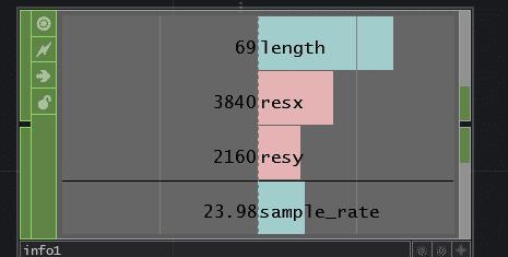
Movie File In
画像、動画ファイルを選択することができる。
info CHOPで選択して、
lengthを見るとフレーム数を見ることができる。
sample_rateでfpsを見ることができる。
indexで現在の再生フレーム
Play ModeでLockded to Timelineにすると現在のタイムライン設定に依存した形で再生される。
Math
input同士の対応するピクセルの演算を置こうなうことができる。
CGソフトでもよくある、Linear workflowとして、計算を素直にすることができるLinearに変換することができる。
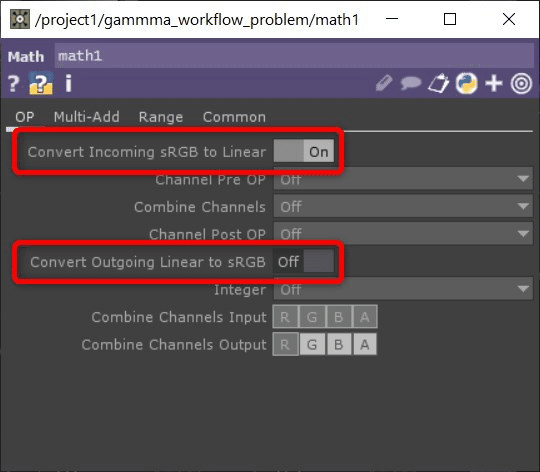
Convert Incoming sRGB to Linear で sRGB を Linear に変換、Convert Outgoing Linear to sRGB で Linear を sRGB に変換します。
[引用] https://zenn.dev/satoruhiga/articles/34ae3d42aae0c3?fbclid=IwAR3F8h1wkpNSLeIqI-6khHlPXO5eo0TAQqk1QSbNn_85LAOfs7zqh-x97go
TouchDesignerではOpenGLを使ってレンダリングをしますが、OpenGLでは数字を Linear(光) として計算するので、レンダリング後はLinearのカラースペースになっています。なので、Render TOP の後に Math TOP で sRGB(色) に変換してあげないといけません。
逆に、テクスチャとして画像を使う時には sRGB(色) を Linear(光) に変換してマテリアルにアサインします。Movie File In TOP を使うのであれば、Image > Input is sRGB のトグルを入れると読み込み時に自動で Linear に変換してくれるのでそちらでもOKです。
[引用] https://zenn.dev/satoruhiga/articles/34ae3d42aae0c3?fbclid=IwAR3F8h1wkpNSLeIqI-6khHlPXO5eo0TAQqk1QSbNn_85LAOfs7zqh-x97go
Movie File Out
Compにローカルタイムラインを設けていて、
メインタイムラインとは別で動いているとき
メインタイムラインが再生されていなくても、ローカルタイムラインが更新されることによって絵は更新されていくような状況の場合、
Recordを押してメインタイムラインを再生していなかったらまだ記録されない。
メインタイムラインを再生して初めて記録され始める。
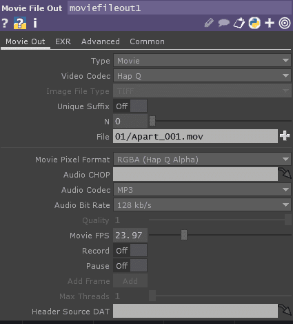
fileは拡張子までしっかり記述した形になっていないとexportがうまくいかない。
Nを使いたいときは自分でme.par.nなどnを混ぜるように書いてあげる
ExportMovieの$Nみたいな書き方はできない。
Nのオートインクリメントも自分で実装してあげないと動かない。
再生の調子がなぜか悪い
フレーム一枚ずつコマ送りでは表示されるが、再生ボタンを押したら描画されないという現象が起きた。
解決方法が分からず、でも書き出したいと思った
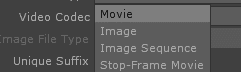
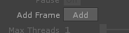
Video CodecをStop-Frame Movieを選択する
下の方にAdd Frameボタンんが出現するんのでタイムラインの+-を押しながら1フレずつ描画してAdd Frameを押すと、押したタイミングの画がフレームとして記録される。
手動で1フレずつやる方法。
Add Frameボタンをkeyboard in CHOPとかと連携させといて押しやすいボタンで操作するとまだ楽。
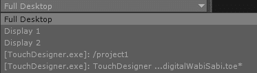
Screen Grab
画面のキャプチャを得ることができる。
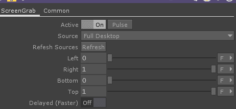
一つだけの画面や、window事のキャプチャなど指定することができる
Left / Right / Bottom / Topでクロップを指定することもできる。
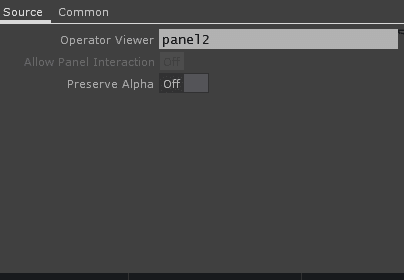
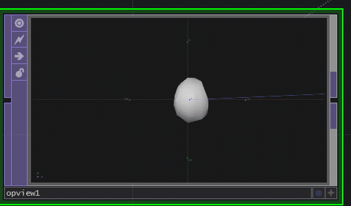
OP Viewer
Operator Viewerに指定したOPのViewをそのまま得ることができる
OPなので、SOPでもTOPでもDATでもCHOPでも基本的に何でも行ける。
Depth
3D空間のDepthをとることができる。
こんなRender TOPがあったとして、
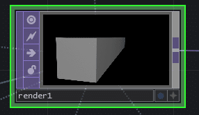
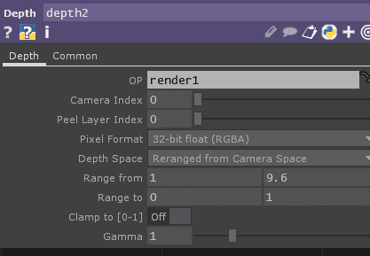
Depth TOPの OPにRender TOPを入れて、
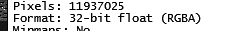
Pixel Format を 32bit RGBA
Depth Space を Reranged from Camera Space
にするとアルファで穴が空いたようになるので
Range fromでDepth距離を決めてあげる。
良い感じのDepth画像を作れる。
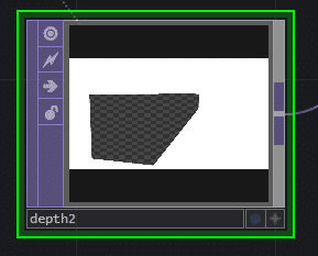
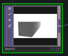
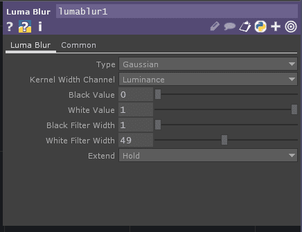
これをLuma Blurとかに入れると
Camera COMPで設定できない、DoF(被写界深度)が作れる。


Depth TOPは、指定されたRender TOPに記述されたシーンから深度情報を含む画像を読み込みます。結果として得られる画像は、表面が近距離の深度値(カメラのパラメータ “Near”)にあるピクセルでは黒(0)になります。また、表面が遠方の深度値(カメラのパラメータ “Far”)にあるピクセルでは、白(1)になります。
Depth TOPはシャドウマッピングを行うために使用されます。他にも、深さを基準にしたエッジ検出など、様々な用途があります。
深さの範囲は、定義上、近距離平面→遠距離平面となります。Depth TOPの値は、近平面では0、遠平面では1になります。一般的にDepth TOPの画像は、平面がオブジェクトの周りに本当に密着していない限り、白になります。しかし、視覚的に何も見えないからといって、情報がないわけではありません。
もう1つのオプションは、Linear Camera-Space Depthです。Render TOPのDepth Buffer Formatが32ビット浮動小数点に設定されていて、Linear Camera-Space Depthパラメータがオンの場合、Depth TOPはリニアなカメラ空間深度を出力します。
Level TOPを使用してDepth TOPの値をリレンジすることができます。ただし、Level TOPのPixel Formatを16または32ビットに設定しないと、Depth TOPのデータから多くの情報が失われます(Depth TOPは24ビットのデータを持っています)。
Depth TOP は、24 ビット固定小数点または 32 ビット浮動小数点のシングルチャンネル画像を作成します。Depth TOP を他の TOP への入力として使用する場合、そのデータは RGBA 値 (D, D, D, D, 1) のように扱われます。GLSL シェーダで Depth テクスチャをサンプリングする場合も同様です。
[引用] http://ted-kanakubo.com/touchdesigner-jp/?p=53
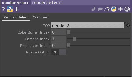
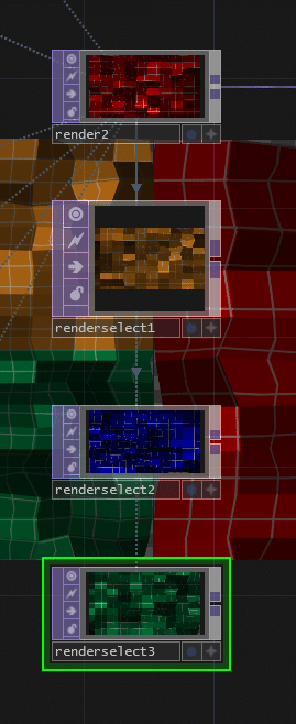
Render select
GLSLのRender Selectの使いかはこっち
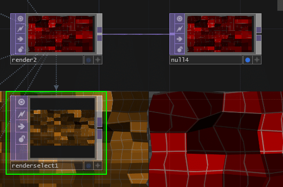
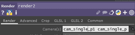
Render TOPのカメラをたくさん指定していた場合、
Render Selectの
TOPにrender TOPを選択すると
Color Buffer Indexを0にして
Camera Indexを変えるとCameraが切り替わる
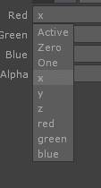
Point File in
点群データ plyファイルを使いたいときに使える。
Point File In TOPは、.obj、.ply、.fits(天文学フォーマット)、.exrを含む様々なメッシュや浮動小数ポイントデータファイルからポイントデータを読み込みます。また、1行に1点、カンマまたはスペースで区切られたフィールドを持つASCIIポイントファイル(.xyz, .pts, .csv, .txtなど)を読み込むこともできます。ASCII ポイントファイルの最初の行には、ポイント数、ポイントフィールドの名前、またはファイルの最初のポイントのいずれかを指定できます。
[引用] http://ted-kanakubo.com/touchdesigner-jp/?p=2630
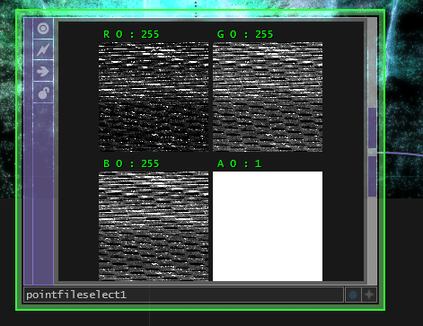
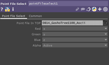
最初にPoint File In TOPでplyファイルを読み込みます。plyファイルをTouchDesignerに直接ドラッグ&ドロップすることもできます。plyファイルは1つの頂点につき複数の情報を持たせることができるのですが、今回利用するのはx、y、z、red、green、blueの6つです。Point File in TOPでは3つまでしか扱えないので残りの3つを扱うためにはPoint File Select TOPを使います。
[引用] https://note.com/toyoshimorioka/n/na8b33b9bf8c3
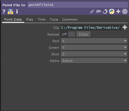
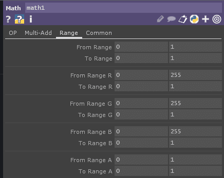
今回作成したplyファイルはRGB値が8bit(0〜255の256段階)なのですが、読み込んだ際に32bit扱いで読み込まれています。なのでMath TOPのRangeを使って0から255を0から1になるようにマッピングします。
[引用] https://note.com/toyoshimorioka/n/na8b33b9bf8c3
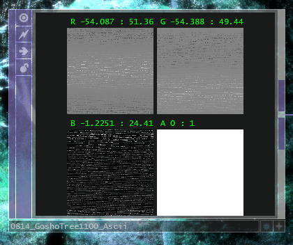
Viwerに表示されているのはR G B Aのチャンネル
最小値 : 最大値
Point File Select
最初にPoint File In TOPでplyファイルを読み込みます。plyファイルをTouchDesignerに直接ドラッグ&ドロップすることもできます。plyファイルは1つの頂点につき複数の情報を持たせることができるのですが、今回利用するのはx、y、z、red、green、blueの6つです。Point File in TOPでは3つまでしか扱えないので残りの3つを扱うためにはPoint File Select TOPを使います。
[引用] https://note.com/toyoshimorioka/n/na8b33b9bf8c3
Lookup
input0にTOP画像
input1にルックアップテーブルとなるTOPいれて
Lookupテーブルにヒットするものをoutputする
4つのチャネルすべてが独自のルックアップを行うため、たとえば、ルックアップによってRedチャネルが変更されが、GおよびBのチャネルはフラットな0-1ランプで値は変更されないような場合もあります。
[引用] http://ted-kanakubo.com/touchdesigner-jp/?p=67
Dark UV / darkuv
ルックアップテーブルのダークエンドに使用するUV位置を設定します。1番目の入力に接続された元のイメージで(0,0,0)の値を持つピクセルは、2番目の入力に接続された画像のこのUV位置にある値で置き換えられます。
Light UV / lightuv
ルックアップテーブルのライトエンドに使用するUV位置を設定します。1番目の入力に接続された元のイメージで(1,1,1)の値を持つピクセルは、2番目の入力に接続された画像のこのUV位置にある値で置き換えられます。
[引用] http://ted-kanakubo.com/touchdesigner-jp/?p=67
Light UV と Dark UVはLookup tableのTOPのUV座標を2点指定して、
R/G/B = [0]のところをDark UVの座標の色、R/G/B = [1]をLight UVの座標の色、中間の明るさの部分は二点のUV座標の線形補間された座標の色となる。
具体例は下の動画が分かりやすい。
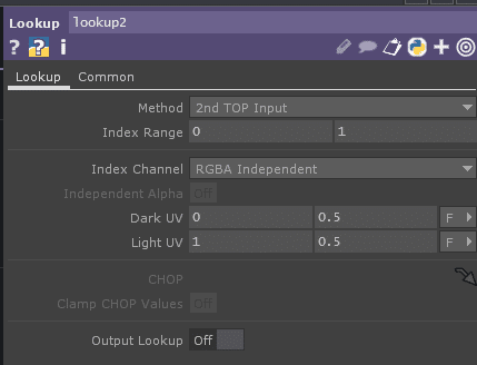
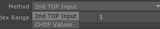
Method
2nd TOP Input (2nd Input, UV Coordinate)はinput1のTOPを使う
CHOP ValuesはCHOPの欄にCHOPを指定して、
ルックアップテーブルはRGBA(Aは任意)を定義する
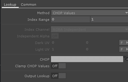
Clamp CHOP Valuesは
CHOP 値を 0~1 の間でクランプします。
Output Lookupは
Lookupテーブルとなっているinput1を出力する。
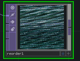
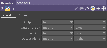
Reorder
inputが4つある。
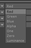
output RGBAをどのinputの何のチャンネルを使うのかを設定できる。
Cross
Cross TOPは、Crossパラメータ(Cross_value)の値に基づいて、2つの入力画像間のブレンドを行います。
Output = Input1*(1-*Cross_value*) + Input2*(*Cross_value*)
Cross / cross
各入力が出力に追加される量を決定します。Cross = 0 の時、Input1 が出力され、Cross = 1 の時、Input2 が出力される。
[入力] http://ted-kanakubo.com/touchdesigner-jp/?p=225
Substract
The Subtract TOP composites the input images together by subtracting the pixel values.
Output = Input1 – Input2. The pixel values below 0 are clammped to 0.
Subtract TOPは、入力画像をピクセル値を減算して合成します。
出力 = 入力1 – 入力2. 0以下の画素値は0になります。
[引用] http://ted-kanakubo.com/touchdesigner-jp/?p=191
input1 - input2になる。
0以下は出力されないと書いてあるが、
Pixel Formatを32bitなどにすればちゃんとマイナスが出てくる。
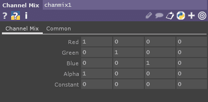
Channel Mix
photoshopでいうチャンネルミキサーと同じような効果
Davinci ResolveでいうRGBミキサー
Channel Mix TOP は、入力RGBAチャンネルを出力の他のカラーチャンネルにミックスすることができます。例えば、入力の青チャンネルのピクセルを出力の赤チャンネルに追加したり、Redパラメータの青の列の値で加算または減算したりすることができます。
[引用] http://ted-kanakubo.com/touchdesigner-jp/?p=232

Luma Level
Levelと基本的には同じ機能だが、違う部分は
チャンネルに機能を適用させることができる。
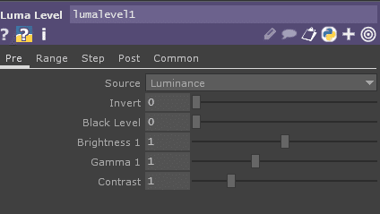
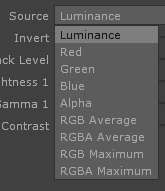
Source を Greenにした場合
グリーチャンネルのTOPの

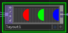
Layout
inputを順番に配置するTOP
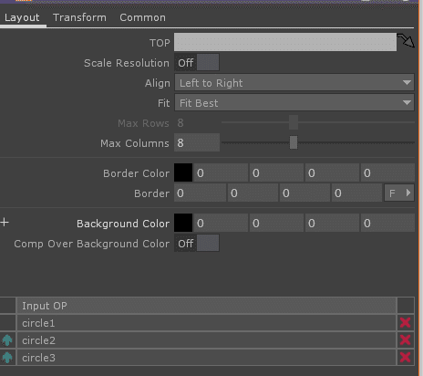
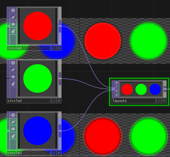
Alignで配置規則を選択できる。
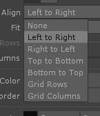
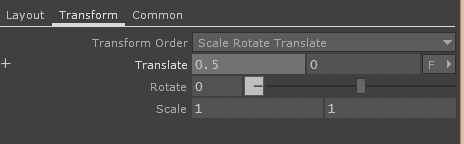
Transformタブで配置されているものに対してTransformを適用できる。
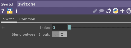
Swtich
Blend between InputsをONにしていると、中間の値のときにBlendするような結果を出してくれる。
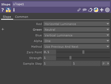
Slope
Slope TOP は、その値と隣接するピクセルの値との差を表すピクセルを生成します。ピクセルの値が0から1の間であることを考えると、0.5の値は、隣接するピクセルの値がそのピクセルの値と同じであることを意味します。赤チャンネルに出力される値が0.5を超えている場合、値が左から右に増加していることを示します。青色のチャンネルで出力される値が0.5以上の場合は、値が下から上に向かって増加していることを示します。
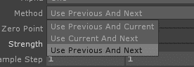
Method / method
イメージの各ピクセルのスロープを計算する際に使用するピクセルを設定します。
Use Previous And Current / prevcur
スロープの計算に前と現在のピクセルを使用します。
Use Current And Next / curnext
スロープの計算に現在のピクセルと次のピクセルを使用します。
Use Previous And Next / prevnext
スロープの計算に前後のピクセルを使用します。
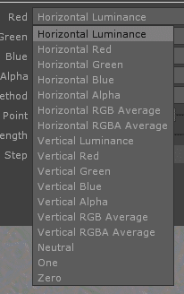
RED / Green / Blue / Alphaにそれぞれ何を出力するかを選べる。
近接のピクセル対してのHorizontal か Verticalの差に応じてLuminance / Red / Green / Blueとして、出力する。
0.5を基準にして、大きい場合のmaxは1、小さい場合のmaxは0と出力する。
Methodで
どのピクセルで実際計算して出力するかを選べる。
Previous and Currentは前のピクセルと現在のピクセル
Current and Nextは現在と次のピクセル
PreviousとNextは前と次のピクセル
から差分を計算する。
端っこがどうゆう処理をされているのかはちょっとわかっていない。
Zero pointが初期値は0.5になっている。
slope計算後に0になるつまり、同じピクセルだったら、0.5を出力するようにする。
これをいじると中間点の位置が変わる。0にすれば大きいときしか出ない。
Sets the value to output when the slope is zero, similar to a midpoint. Default is .5 since 8-bit pxels are 0 to 1. But with Pixel Format et to 32-bit Float you should set this to 0, and look at the view in Normalized Split mode.
傾きが 0 のときに出力する値を設定します(中間点のようなもの)。8bit pxelは0〜1なのでデフォルトは0.5ですが、Pixel Format et to 32-bit Floatでは0に設定し、Normalized Split Modeで表示するとよいでしょう。
StregthはSlopeで出力する値に対してStrengthで設定した乗数が掛け算される。初期値1でそのままの値が出力される。
Sample stepはどのくらい距離があるピクセルで計算するかを設定できる。初期値は1/1pixelになっているから直近の隣のピクセルが選ばれる。

この記事が気に入ったらサポートをしてみませんか?