PIC18F27Q43 プログラミング2割り込み処理

前回、オシレータをFosc=32Mhzに設定しました。今回は、Timer0を使った割り込みでLEDを点滅させます。
0.従来のPICの割り込み処理
従来の16F、18F系PICマイコンの割り込みは、 割込発生時に飛んでいく割り込み処理ルーチンの開始アドレスが0004hの一つだけでした。そこから実行させる割り込み処理関数も一つだけだったので、その中で、タイマー割り込み、外部入力割り込み、AD割込みなど、すべての割り込みをフラグを見て、各々の割り込み処理を、たった一つの関数で行っていました。
1.VIC Vectored Interrupt Controller Module
18F27Q43は、各々の割り込みが、固有の割り込み関数登録アドレスを持てるようになりました。それに伴って、割込みアドレスの管理が必要になります。また、複数の割り込みが同時に発生した場合の処理を考える必要があります。
また、従来のPICと同じように一つの割り込みアドレスで、処理を行うこともできます。
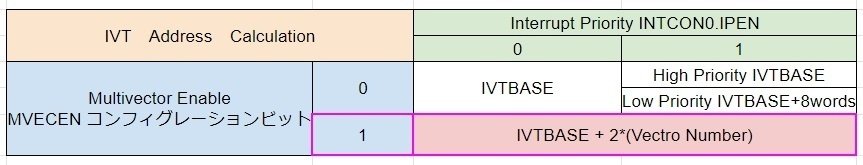
コンフィグレーションビット MVECEN とINTCON0レジスタIPENビットの値で選択します。今回は、MVECEN=1 と設定したので、割込みベクターテーブルを採用しています。
1.1 Interrupt Vector Tabel(IVT) 割込みベクタアドレステーブル
vectorという単語は、数学のベクトルを通常意味するのですが、プログラミングでは、配列や連続したメモリエリアを意味します。割り込み処理関数である割込みハンドラは複数あります。登録アドレスも複数存在しています。この登録されたエリアを、割込みベクタテーブルと呼んでいます。
このベクター番号が、実行優先順位にもなっています。
1.2 IVTBASE 割込みベクタの先頭アドレス
ユーザーが割り込みベクタの先頭アドレスを指定します。Lockがかかっているので、解除してからアドレスを指定します。PIC18FのデフォルトのIVTBASEアドレスは、0008hです。このアドレスを使ったほうが無難だと思います。以下のコードで設定しています。
///Vector Interrupt Controller Module
//config MVECEN = ON  multivector.
//config IVT1WAY = ON setting only once .
//IVT address Caluculation IVBASE + 2*(Vector Number)
void vicInit(void)
{
    //割り込みテーブルaddress設定----------------------------------
    INTCON0bits.GIE=0;//Enable all masked interrupts
    IVTLOCK=0x55;
    IVTLOCK=0xAA;
    IVTLOCKbits.IVTLOCKED=0;
    IVTBASE = 0x000008;
    IVTLOCK=0x55;
    IVTLOCK=0xAA;
    IVTLOCKbits.IVTLOCKED=1;
    //グローバル割り込み許可------------------------------------------
    INTCON0bits.IPEN=0;//プライオリティ無し
    INTCON0bits.GIE=1;//Enable all masked interrupts
}
設定したら、再び、ロックをかけています。(datasheet P.120)
1.3 多重割込み時のVICの処理方法
同時に複数の割り込みが発生した場合、マイコンの仕様によっては、スタックがオーバーフローする可能性があります。データシート(DS40002147E-page.123)を読むと、PIRxレジスタのフラグが1になった割り込みはすべて、処理の順番を待って、実行されます。割り込み処理中に、別の割り込みが発生する場合の処理、中断して、優先度の高い割り込みが実行されます。
短時間に多数の割り込みが発生する場合、mainに制御がなかなか戻らなかったり、スタックオーバーフローが起こる可能性がありそうです。同時に発生する割り込みの数を少なくしたほうが、無難です。
2.XC8 割込み処理関数の記述
MPLAB® XC8 C Compiler User’s Guide P.34
2.5.10 Interrupt Functions The __interrupt(type) specifier can be used to indicate that a function is to act as an interrupt service routine. The type is a comma-separated list of keywords that indicate information about the interrupt function
<略>
irq(irqid) Specify the interrupt vector associated with this interrupt. (MPLAB XC16 and XC8
//****************割り込み関数***********************//
// Timer0割込み
//**************************************************//
void __interrupt(irq(IRQ_TMR0)) Timer0_ISR(void)
{
    PIR3bits.TMR0IF=0;
    tm0.cnt++;
    TMR0L=0xF0;//10ms interval
    if(tm0.cnt==50)
    {
        tm0.cnt=0;
        tm0.fg=true;
        //TMR0 停止処理
        T0CON0bits.EN=0;
        PIE3bits.TMR0IE=0;
    }
}
__interrupt(type)指定子で、その関数が割り込みハンドラであることを明示します。typeには、irq(irqid)を指定します。irqidはベクター番号になります。
MPLABのエディターで、キーボードのCTRLボタンを押しながら、IRQ_TMR0の上にマウスでカーソルを合わせます。青いラインが出るので、クリックすると、ベクター番号がdefine定義されたファイルpic18F27q43.hにジャンプしてくれます。define定義されたラベルを参考に各々のirqidを指定します。
Timer0の場合、#define IRQ_TMR0 31 と定義されています。
#define IRQ_DMA1A 23
// SPI1 Receive Interrupt
#define IRQ_SPI1RX 24
// SPI1 Transmit Interrupt
#define IRQ_SPI1TX 25
// SPI1 Interrupt
#define IRQ_SPI1 26
// Timer2 Interrupt
#define IRQ_TMR2 27
// Timer1 Interrupt
#define IRQ_TMR1 28
// Timer1 Gate Interrupt
#define IRQ_TMR1G 29
// CCP1 Interrupt
#define IRQ_CCP1 30
// Timer0 Interrupt
#define IRQ_TMR0 31
// UART1 Receive Interrupt
#define IRQ_U1RX 32
// UART1 Transmit Interrupt
#define IRQ_U1TX 33
// UART1 Error Interrupt
#define IRQ_U1E 34
// UART1 Interrupt
#define IRQ_U1 35
// PWM1 Period Interrupt
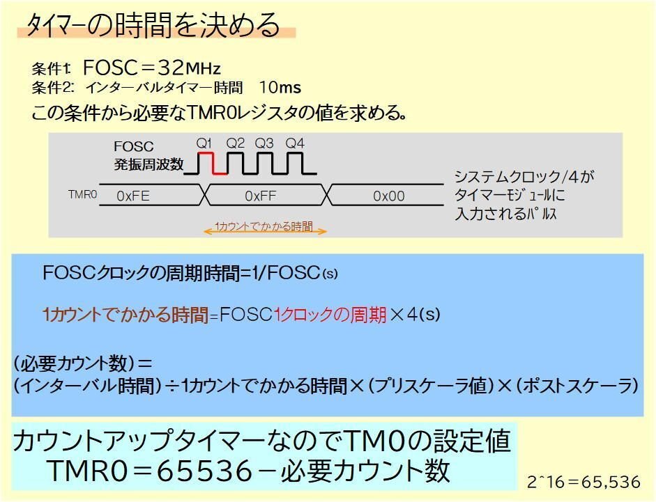
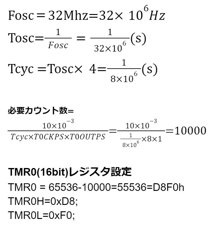
#define IRQ_PWM1PR 383.タイマー0の設定値 10msインターバル
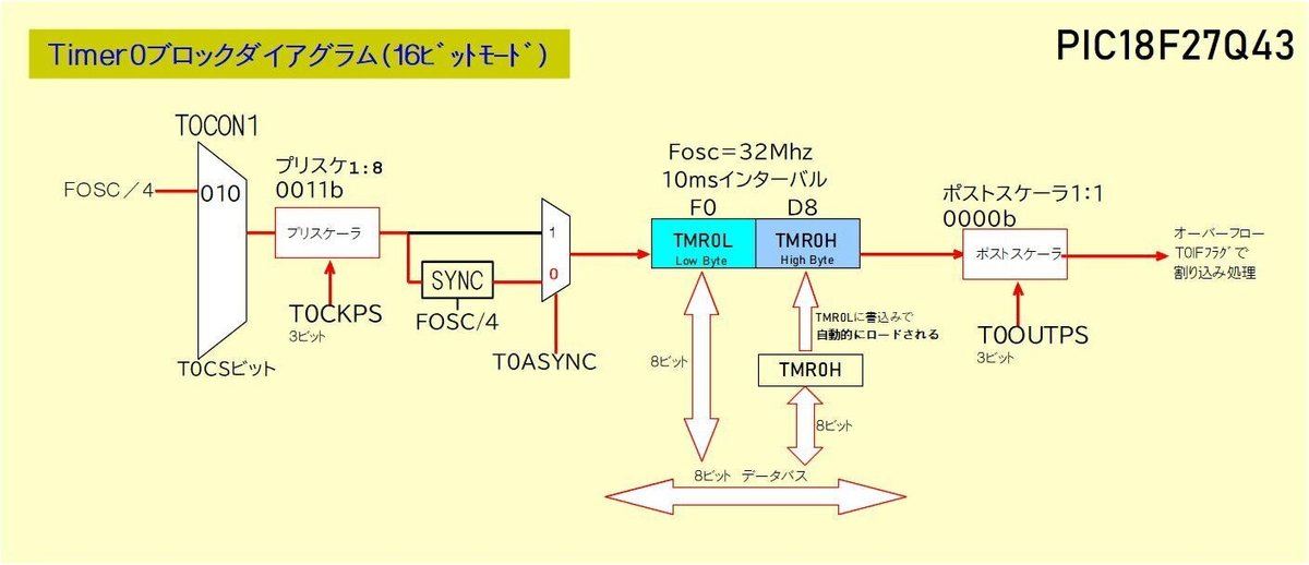
システムクロックFosc=32Mhzで設定しています。
Timer0の割り込みインターバル時間を10msに設定します。
プリスケーラは1:8、ポストスケーラは1:1に設定します。
4.コード
// PIC18F27Q43 Configuration Bit Settings

// 'C' source line config statements

// CONFIG1
#pragma config FEXTOSC = OFF    // External Oscillator Selection (Oscillator not enabled)
#pragma config RSTOSC = HFINTOSC_64MHZ// Reset Oscillator Selection (HFINTOSC with HFFRQ = 64 MHz and CDIV = 1:1)

// CONFIG2
#pragma config CLKOUTEN = OFF   // Clock out Enable bit (CLKOUT function is disabled)
#pragma config PR1WAY = OFF     // PRLOCKED One-Way Set Enable bit (PRLOCKED bit can be set and cleared repeatedly)
#pragma config CSWEN = ON       // Clock Switch Enable bit (Writing to NOSC and NDIV is allowed)
#pragma config FCMEN = OFF      // Fail-Safe Clock Monitor Enable bit (Fail-Safe Clock Monitor disabled)

// CONFIG3
#pragma config MCLRE = EXTMCLR  // MCLR Enable bit (If LVP = 0, MCLR pin is MCLR; If LVP = 1, RE3 pin function is MCLR )
#pragma config PWRTS = PWRT_OFF // Power-up timer selection bits (PWRT is disabled)
#pragma config MVECEN = ON      // Multi-vector enable bit (Multi-vector enabled, Vector table used for interrupts)
#pragma config IVT1WAY = ON     // IVTLOCK bit One-way set enable bit (IVTLOCKED bit can be cleared and set only once)
#pragma config LPBOREN = OFF    // Low Power BOR Enable bit (Low-Power BOR disabled)
#pragma config BOREN = SBORDIS  // Brown-out Reset Enable bits (Brown-out Reset enabled , SBOREN bit is ignored)

// CONFIG4
#pragma config BORV = VBOR_1P9  // Brown-out Reset Voltage Selection bits (Brown-out Reset Voltage (VBOR) set to 1.9V)
#pragma config ZCD = OFF        // ZCD Disable bit (ZCD module is disabled. ZCD can be enabled by setting the ZCDSEN bit of ZCDCON)
#pragma config PPS1WAY = OFF     // PPSLOCK bit One-Way Set Enable bit (PPSLOCKED bit can be cleared and set only once; PPS registers remain locked after one clear/set cycle)
#pragma config STVREN = ON      // Stack Full/Underflow Reset Enable bit (Stack full/underflow will cause Reset)
#pragma config LVP = ON         // Low Voltage Programming Enable bit (Low voltage programming enabled. MCLR/VPP pin function is MCLR. MCLRE configuration bit is ignored)
#pragma config XINST = OFF      // Extended Instruction Set Enable bit (Extended Instruction Set and Indexed Addressing Mode disabled)

// CONFIG5
#pragma config WDTCPS = WDTCPS_31// WDT Period selection bits (Divider ratio 1:65536; software control of WDTPS)
#pragma config WDTE = OFF       // WDT operating mode (WDT Disabled; SWDTEN is ignored)

// CONFIG6
#pragma config WDTCWS = WDTCWS_7// WDT Window Select bits (window always open (100%); software control; keyed access not required)
#pragma config WDTCCS = SC      // WDT input clock selector (Software Control)

// CONFIG7
#pragma config BBSIZE = BBSIZE_512// Boot Block Size selection bits (Boot Block size is 512 words)
#pragma config BBEN = OFF       // Boot Block enable bit (Boot block disabled)
#pragma config SAFEN = OFF      // Storage Area Flash enable bit (SAF disabled)
#pragma config DEBUG = OFF      // Background Debugger (Background Debugger disabled)

// CONFIG8
#pragma config WRTB = OFF       // Boot Block Write Protection bit (Boot Block not Write protected)
#pragma config WRTC = OFF       // Configuration Register Write Protection bit (Configuration registers not Write protected)
#pragma config WRTD = OFF       // Data EEPROM Write Protection bit (Data EEPROM not Write protected)
#pragma config WRTSAF = OFF     // SAF Write protection bit (SAF not Write Protected)
#pragma config WRTAPP = OFF     // Application Block write protection bit (Application Block not write protected)

// CONFIG10
#pragma config CP = OFF         // PFM and Data EEPROM Code Protection bit (PFM and Data EEPROM code protection disabled)

// #pragma config statements should precede project file includes.
// Use project enums instead of #define for ON and OFF.

#include <xc.h>
#include <stdio.h>
#include <stdlib.h>
#include <stdint.h>

#include <stdbool.h>

#define _XTAL_FREQ 32000000

void portInit(void);
void oscillatorInit(void);
void vicInit(void);

//Timer制御構造体
typedef struct
{
    uint8_t cnt; //タイマー用カウンタ
    bool    fg;  //カウントアップフラグ
}TimerInfo;

TimerInfo tm0;


//****************割り込み関数***********************//
// Timer0割込み
//**************************************************//
void __interrupt(irq(IRQ_TMR0)) Timer0_ISR(void)
{
    PIR3bits.TMR0IF=0;
    tm0.cnt++;
    TMR0L=0xF0;//10ms interval
    if(tm0.cnt==50)
    {
        tm0.cnt=0;
        tm0.fg=true;
        //TMR0 停止処理
        T0CON0bits.EN=0;
        PIE3bits.TMR0IE=0;
    }
}

//*********************************************
//Timer0 初期化
//*********************************************
void timer0Init(void)
{
    //Clock Source Select
    T0CON1bits.CS=0b010;//クロックソースFosc/4
    //Prescaler Rate Select
    T0CON1bits.CKPS=0b0011;//プリスケ1:8
    //8-bit or 16-bit Timer Operation Select
    T0CON0bits.MD16=1;//16bitsタイマー
    //Output Postscaler Select
    T0CON0bits.OUTPS=0b0000;//ポストスケーラ1:1
    //Period/Count High and Low Register
    TMR0H=0xD8;//10ms Fosc=32Mhz
    TMR0L=0xF0;//10ms
    //TMR0 Enable
    T0CON0bits.EN=1;
    //TMR0 interrupt controler
    PIE3bits.TMR0IE=1;
    PIR3bits.TMR0IF=0;
    //Timer0変数初期化
    tm0.cnt=0;
    tm0.fg=false;
}

void main(void)
{
    uint8_t ledVal;
    //CPUハード初期化-----------------------
    portInit();
    oscillatorInit();
    //Peripheral初期化---------------------
    timer0Init();

    //vector割り込み設定-------------------
    vicInit();


    ledVal=0x01;
    while(1)
    {
        if(tm0.fg)
        {
            tm0.fg=false;
            LATAbits.LATA0=~LATAbits.LATA0;
            LATB=ledVal;
            ledVal<<=1;
            if(ledVal==0x40)
            {
                ledVal=0x01;
            }
            //timer0 再起動
            T0CON0bits.EN=1;
            PIE3bits.TMR0IE=1;
        }
    }
    return;
}

void portInit(void)
{
    PORTA=0x00;
    LATA=0x00;
    ANSELA=0x00;
    TRISA=0x00;

    PORTB=0x00;
    LATB=0x00;
    ANSELB=0x00;
    TRISB=0x00;

    PORTC=0x00;
    LATC=0x00;
    ANSELC=0x00;
    TRISC=0x00;

}

void oscillatorInit(void)
{
    //オシレータ設定----------------
    OSCCON3bits.CSWHOLD=1;    //Hold
    OSCCON1bits.NDIV=1;       //64Mhz/2=32Mhz;
    while(!OSCCON3bits.NOSCR);//NewOscillatroReady?
    while(!PIR0bits.CSWIF);   //Clock Switch Interrupt Flag
    PIR0bits.CSWIF=0;         //Clear by software
    OSCCON3bits.CSWHOLD=0;    //NewOsc proceed.
    while(!OSCCON3bits.ORDY);
}


///Vector Interrupt Controller Module
//config MVECEN = ON  multivector.
//config IVT1WAY = ON setting only once .
//IVT address Caluculation IVBASE + 2*(Vector Number)
void vicInit(void)
{
    //割り込みテーブルaddress設定----------------------------------
    INTCON0bits.GIE=0;//Enable all masked interrupts
    IVTLOCK=0x55;
    IVTLOCK=0xAA;
    IVTLOCKbits.IVTLOCKED=0;
    IVTBASE = 0x000008;
    IVTLOCK=0x55;
    IVTLOCK=0xAA;
    IVTLOCKbits.IVTLOCKED=1;
    //グローバル割り込み許可------------------------------------------
    INTCON0bits.IPEN=0;//プライオリティ無し
    INTCON0bits.GIE=1;//Enable all masked interrupts
}
この記事が気に入ったらサポートをしてみませんか?