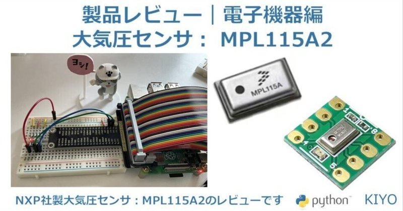
製品レビュー|電子機器11:大気圧センサ(MPL115A2)

1.概要
購入した製品の使い方および感想用記事です。
今回は「MPL115A2使用大気圧センサーモジュールキット(I2C) Ver.2(600円/個(税込))」をレビューしました。
※現在(@2024/5/2)全部のエラーがとれていないため、必要部品揃えてから追記予定

1-1.基本仕様
freescale社の超小型大気圧センサーを使いやすいDIP(Dual Inline Package)モジュール化しています。
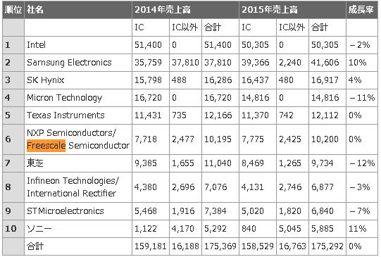
【コラム:Freescale社とは】
フリースケール・セミコンダクタ(Freescale Semiconductor, Inc.)は、2004年にモトローラ社の半導体部門が分離して設立されたアメリカの半導体製造企業です。
2015年12月にオランダのNXPセミコンダクターズに買収されています。
1-1-1.仕様の概要
基本の概要は下記参照。
電源電圧:DC2.375-5.5V
測定気圧:50~115 kPa ±1
インターフェース:I2C(最大400kHz)
ADC搭載, 温度も計測可
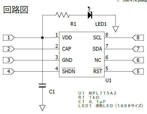
1-1-2.ピン配置
ピンの配置は下図の通り

1-2.詳細仕様
1-2-1.ブロック図

1-2-2.シーケンスフロー
一連の動作図は下図の通り
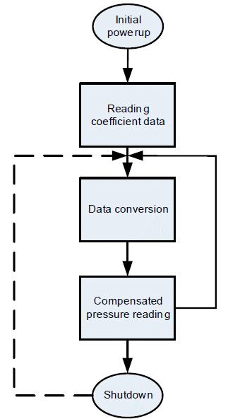
Initial power-up:
All circuit elements are active. I2C port pins are high impedance and associated registers are cleared. The device then enters standby mode.Reading coefficient data:
The user then typically accesses the part and reads the coefficient data. The main circuits within the slave device are disabled during read activity. The coefficients are usually stored in the host microcontoller local memory but can be re-read at any time.
It is not necessary to read the values stored in the host microcontroller multiple times because the coefficients within a device are constant and do not change. However, note that the coefficients will be different from device to device, and cannot be used for another part.Data conversion:
This is the first step that is performed each time a new pressure reading is required which is initiated by the host sending the CONVERT command. The main system circuits are activated (wake) in response to the command and after the conversion completes, the result is placed into the Pressure and Temperature ADC output registers.
The conversion completes within the maximum conversion time, tc. The device then enters standby mode.Compensated pressure reading:
After the conversion has been given sufficient time to complete, the host microcontroller reads the result from the ADC output registers and calculates the Compensated Pressure, a barometric/atmospheric pressure value which is compensated for changes in temperature and pressure sensor linearity. This is done using the coefficient data from the MPL115A and the raw sampled pressure and temperature ADC output values, in a compensation equation (detailed later). Note that this is an absolute pressure measurement with a vacuum as a reference.
From this step the host controller may either wait and then return to the Data Conversion step to obtain the next pressure reading or it may go to the Shutdown step.Shutdown:
For longer periods of inactivity the user may assert the SHDN input by driving this pin low to reduce system power consumption. This removes power from all internal circuits, including any registers. In the shutdown state, the Pressure and Temperature registers will be reset, losing any previous ADC output values.
This step is exited by taking the SHDN pin high. Wait for the maximum wakeup time, tw, after which another pressure reading can be taken by transitioning to the data Conversion step.
1-2-3.メモリ/コマンドマップ
デバイスのメモリマップは下表の通り


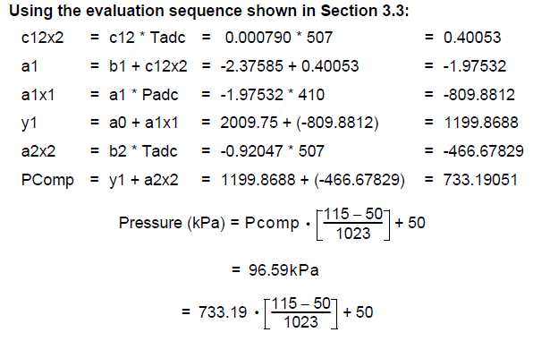
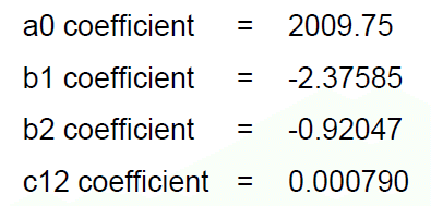
1-2-4.計算方法

2.製品原理
製品の動作原理に関する部分を説明します。
2-1.MEMSとは
「MPL115A2はMEMS圧力センサを採用している」と記載があります。
MEMS(Micro Electro Mechanical Systems:微小電気機械システム)とは、半導体のシリコン基板・ガラス基板・有機材料などに、機械要素部品のセンサ・アクチュエータ・電子回路などをひとまとめにしたミクロンレベル構造を持つデバイスを指します。
一般的には全長がmm単位で、その部品はµm単位という世界です。

MEMSプロセスは、成膜工程、フォトリソグラフィ工程、エッチング工程など、一般的な半導体プロセスフローを基本としています。

2-2.測定原理
圧力センサは下図の通り複数の検知方式があります。

正確な測定原理の記載が見当たりませんが、MEMS圧力センサと言えば下記2種とのことです。
ピエゾ抵抗型:応力によるダイアフラムのたわみを検出し、その応力を電気信号に変換
静電容量型:ダイアフラムのたわみを電気信号に直接変換

おそらく静電容量型を使用しており、圧力によりダイアフラムがたわむとダイアフラム電極と対向電極による静電容量が変化するため、この容量変化を検出して圧力に変換しています。

3.部材購入
3-1.購入品
部品は本体のみ購入しました。
3-2.準備必須品
その他必需品は下記の通りです。
マイコン/シングルボード(Raspberry Pi/Pico)
ブレッドボード
ジャンピングワイヤー
4.環境構築
4-1.マイコン準備
センサを制御するためのシングルボードやマイコンの準備を行います。
Raspberry PiやPicoの準備は下記記事参照のこと
Raspberry PiにGPIOを制御するためのライブラリが無い場合は”RPi.GPIO”を事前にインストールしておきます。
Picoの場合はMicropythonを使用できるようにしておきます。
[Terminal]
pip install rpi.gpio
4-2.ライブラリのインストール
4-2-1.Case1:Pico
Raspberry Pi Picoは組み込み関数と標準ライブラリで対応できるため、追加の環境構築は不要です。
4-2-2.Case2:Raspberry Pi
RPi.GPIOはシリアル通信のクラスが無いため、I2C用に別途smbus2をインストールします。
[Terminal]
pip install smbus2
なおsmbus2ではある程度スクラッチでコード作成する必要がありますが、Adafruit提供のライブラリを使用すればより簡単に実装できます。

[Terminal]
pip3 install adafruit-circuitpython-mpl115a2
5.使用前の準備
5-1.はんだ付け
本キットは基板とピンソケットが別詰のためはんだ付けしました。

5-2.部品の組付け
部品の組付けはジャンパー線を使用して下記の通り繋ぎました。
なお注意点は下記の通りです。
通常はセンサのPIN2(CAP)に1μFのコンデンサを設置してください。私は手持ちがなかったので設置しませんでした。
コンデンサはPIN2(CAP)とPIN3(GND)に接続
コンデンサは電気を一時的に貯めるものなので、たぶん無くても壊れないと思う(抵抗器のようにつけないとショートの恐れはない??
PIN4(SHDN)とPIN5(RST)にも電源供給をしてください。これをしないとI2C通信確認時にアドレスが確認できませんでした。
仕様書のどこを見たら理解できるのかがわからない。

【Raspberry Pi】
$$
\begin{array}{|c|c|c|} \hline \textbf{No.} &\textbf{センサー} & \textbf{Raspberry Pi} \\
\hline \text{1} & \text{VDD} & \text{PIN1(3.3V)}\\
\hline \text{2} & \text{GND} & \text{PIN9(GND)}\\
\hline \text{3} & \text{SDA} & \text{GPIO2(SDA1 I2C)}\\
\hline \text{4} & \text{SCL} & \text{GPIO3(SCL1 I2C0)}\\
\hline \end{array}
$$

※下図はダイオードが入っていないため、追って差し替え予定です。電源を供給するとセンサのLEDが光ります。

【Raspberry Pi Pico】
$$
\begin{array}{|c|c|c|} \hline \textbf{No.} &\textbf{センサー} & \textbf{Raspberry Pi Pico} \\
\hline \text{1} & \text{VDD} & \text{PIN36(3.3V)}\\
\hline \text{2} & \text{GND} & \text{PIN38(GND)}\\
\hline \text{3} & \text{SDA} & \text{GPIO16(I2C0 SDA)}\\
\hline \text{4} & \text{SCL} & \text{GPIO17(I2C0 SCL)}\\
\hline \end{array}
$$

6.MicroPythonスクリプト(Pico)
Micropythonのコードは下記記事を参考にさせていただきました。
6-1.任意:デバイス接続の確認
I2CクラスのI2C.scan()でデフォルトアドレスを確認しておきます。
[IN]
from machine import Pin, I2C

i2c = I2C(0, scl=Pin(17), sda=Pin(16), freq=400000)
print([hex(i) for i in i2c.scan()])
[OUT]
['0x60']6-2.コードの設計思想
設計思想は下記の通りです。
基本的にはコードを写経しながら仕様書を読解していきます。
設計思想の順番は次項の備忘録に記載
ビット演算やバイト型は下記記事参照
Byte型出力確認のためにASCII文字コード表を下図に記載

6-3.スクリプト実行
追って対応(※現状start conversionのコマンド0x12が通らないエラー発生中▶原因不明のため、まずはダイオード購入してから別途確認)
[IN]
[OUT]
7.Pythonスクリプト(Raspberry Pi)
Raspberry Piでも実行しました。コードは下記記事参照しました。
7-1.任意:デバイス接続の確認
I2C通信の確認は下記コマンドで実施可能です。
[Terminal]
sudo i2cdetect -y 1
7-2.スクリプト実行
Raspberry Piは「adafruit/Adafruit_CircuitPython_MPL115A2」のライブラリを用いて、"examples/mpl115a2_simpletest.py"をほぼそのまま利用しました。
桁数から気圧はhPaでの表示だと思います。
[IN]
import time
import board
import busio
import adafruit_mpl115a2

i2c = busio.I2C(board.SCL, board.SDA) #I2Cオブジェクト作成
mpl = adafruit_mpl115a2.MPL115A2(i2c) #MPL115A2オブジェクト作成

while True:
    print(f'気圧:{mpl.pressure:.2f} hPa, 温度:{mpl.temperature:.2f} ℃')
    time.sleep(1)
[OUT]
気圧:1128.00 hPa, 温度:20.70 ℃
気圧:1076.88 hPa, 温度:15.84 ℃
気圧:981.41 hPa, 温度:15.09 ℃
気圧:1094.66 hPa, 温度:15.09 ℃
気圧:1140.21 hPa, 温度:28.93 ℃
気圧:1069.44 hPa, 温度:29.11 ℃温度にふらつきが確認されました。多分1μFコンデンサを付けてないのが理由かもしれません。(追ってコンデンサを購入予定)

【動作確認用スクリプト】
動作を確認するために”adafruit_mpl115a2.py”から見れる変数を確認するためのprint文追加しました。装置が保持している係数は、おそらく機器ごとの校正結果に合わせているため仕様書とは異なる値と思われます。
a0=1859.12
b1=-2.174927
b2=-0.907593
c12=0.000713
[IN]
import time
import board
import busio
import adafruit_mpl115a2

i2c = busio.I2C(board.SCL, board.SDA) #I2Cオブジェクト作成
mpl = adafruit_mpl115a2.MPL115A2(i2c) #MPL115A2オブジェクト作成

print(f'係数確認:a0{mpl._a0:.2f}, b1{mpl._b1:.2f}, b2{mpl._b2:.2f}, c12{mpl._c12:.2f}', end='\n\n')

while True:
    print(f'気圧:{mpl.pressure:.2f} hPa, 温度:{mpl.temperature:.2f} ℃')
    print(f'Buffer:{mpl._buf}')
time.sleep(1)[OUT]
係数確認:a0=1859.12, b1=-2.174927, b2=-0.907593, c12=0.000713
気圧:1185.22 hPa, 温度:47.43 ℃
Buffer:bytearray(b'2@^\x80')
気圧:1205.39 hPa, 温度:27.06 ℃
Buffer:bytearray(b'I\x00y\xc0')
気圧:1108.52 hPa, 温度:11.92 ℃
Buffer:bytearray(b'0\xc0\x8e\x00')
気圧:1045.16 hPa, 温度:17.90 ℃
Buffer:bytearray(b'2@\x86\x00')
気圧:942.64 hPa, 温度:7.62 ℃
Buffer:bytearray(b'Y\xc0\x93\xc0')
気圧:1093.41 hPa, 温度:20.70 ℃
Buffer:bytearray(b'3\x80\x82@')
気圧:1190.86 hPa, 温度:25.00 ℃
Buffer:bytearray(b'"\x80|\x80')7-3.参考:スクラッチでのスクリプト(SMBUS2)
下記記事を参照し、smbus2でスクラッチで作成しました。
現状値が振れるため正確な数値が確認できていませんが、それっぽい値が出ることは確認しました。
[IN]
import smbus2
import time

def convert_coefficient(msb, lsb, total_bits, fractional_bits, zero_pad):
    data = (msb << 8) | lsb
    period = float(1 << (16 - total_bits + fractional_bits + zero_pad))
    if (msb >> 7) == 0:
        result = float(data / period)
    else:
        result = -float(((data ^ 0xFFFF) + 1) / period)
    return result

def get_hectopascal(bus, verbose=False):
    address = 0x60

    bus.write_byte_data(address, 0x12, 0x01) #Start conversion
    time.sleep(0.003)

    block = bus.read_i2c_block_data(address, 0x00, 12) #Read data

    a0 = convert_coefficient(block[4], block[5], 16, 3, 0)
    b1 = convert_coefficient(block[6], block[7], 16, 13, 0)
    b2 = convert_coefficient(block[8], block[9], 16, 14, 0)
    c12 = convert_coefficient(block[10], block[11], 14, 13, 9)

    padc = (block[0] << 8 | block[1]) >> 6
    tadc = (block[2] << 8 | block[3]) >> 6

    c12x2 = c12 * tadc
    a1 = b1 + c12x2
    a1x1 = a1 * padc
    y1 = a0 + a1x1
    a2x2 = b2 * tadc
    pcomp = y1 + a2x2

    pressure = (pcomp * 65 / 1023) + 50
    temperature = (tadc - 498) / -5.35 + 25  # Convert tadc to temperature
    hectopascal = pressure * 10

    if verbose:
        print(f'block:{block}')
        print(f'a0:{a0:.2f}, b1:{b1:.6f}, b2:{b2:.6f}, c12:{c12:.6f}')
        print(f'padc:{padc}, tadc:{tadc}')

    return hectopascal, temperature

#実行
bus = smbus2.SMBus(1)
P, T = get_hectopascal(bus, verbose=True)
print(f'気圧:{P:.2f} hPa, 温度:{T:.2f} ℃')
[OUT]
block:[49, 128, 132, 0, 58, 25, 186, 103, 197, 234, 46, 180]
a0:1859.12, b1:-2.174927, b2:-0.907593, c12:0.000713
padc:198, tadc:528
気圧:1150.50 hPa, 温度:19.39 ℃8.所感
簡単な所感は下記の通り
今までのセンサより仕様書が難しい+記事が少ないので理解がきつい
ソフトウェア(コード)もしんどいけど、ハードウェアのデータシートも理解が難しい(なぜPIN4(SHDN)とPIN5(RST)に電源供給しないといけないかがデータシートだけからだと理解できない
電子工作していくなら、抵抗器だけでなくコンデンサも必須なのかな・・
参考資料
別添1 Python関係
別添2 技術関係
あとがき
とりあえず下記は追って修正予定
1μFのコンデンサ購入
組図の修正
Micropythonのコードを再実装(現状のエラー原因不明のため、とりあえずハードウェアの設定は完全にしておく)
仕様書(データシート)の読解追記
この記事が気に入ったらサポートをしてみませんか?